Layout Construction Updates for 2006
The Home and Design of the RGW
January 2006
The last couple of weekends we made great strides on the southwest finger table and the two other table sections that comprise the southwest corner of the layout. As you will see in these photos, the basic construction technique is to create a box of 1×4″ dimensional lumber, in our case, pine. From that box, we will use risers to provide the base for our subroadbed. On the finger table itself, the Chief Engineer and I have agreed to use Linn Westcott’s tried and true method of L-girder construction, with a minor twist. In our case, we will eventually make use of special construction brackets rather than rely on the 1×2″ horizontal portion of the “L”.
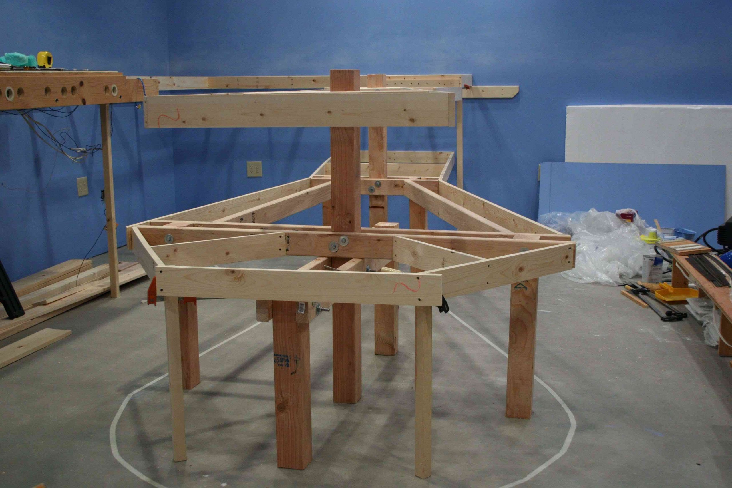
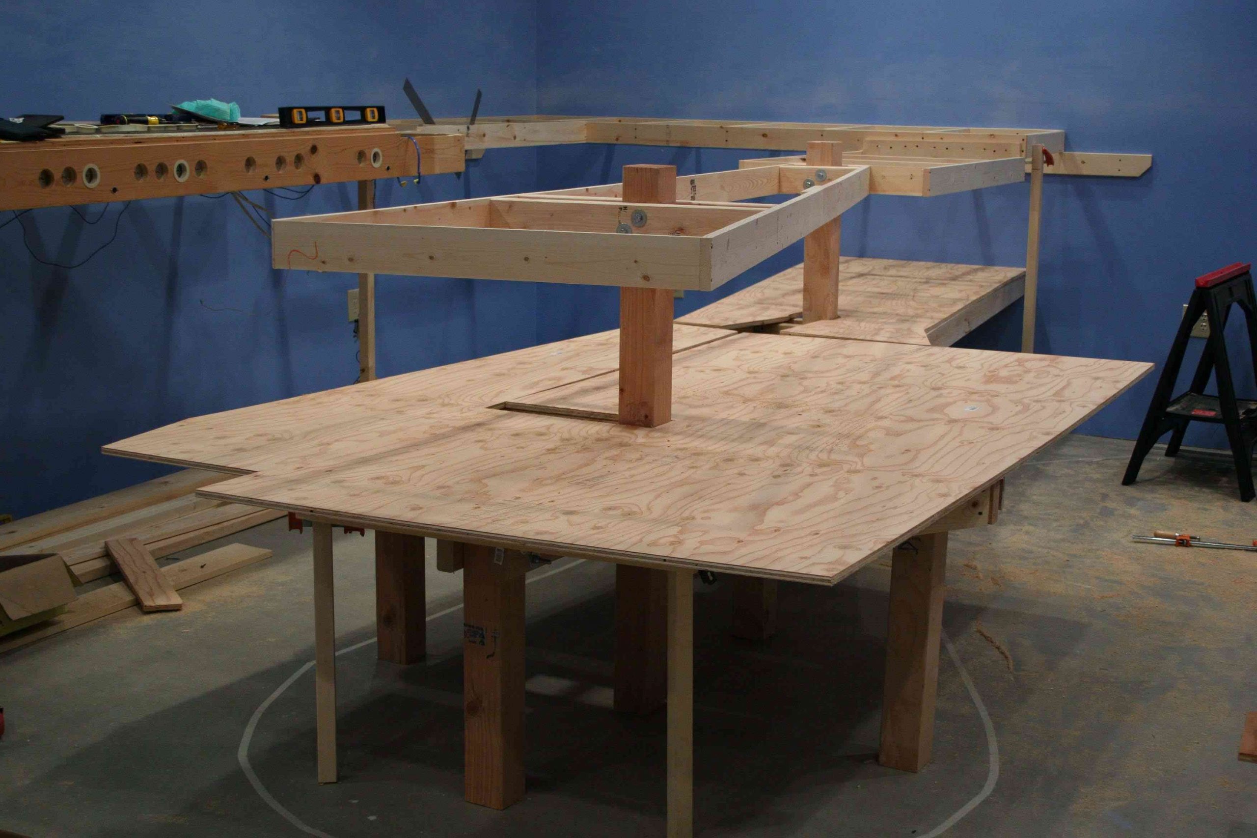
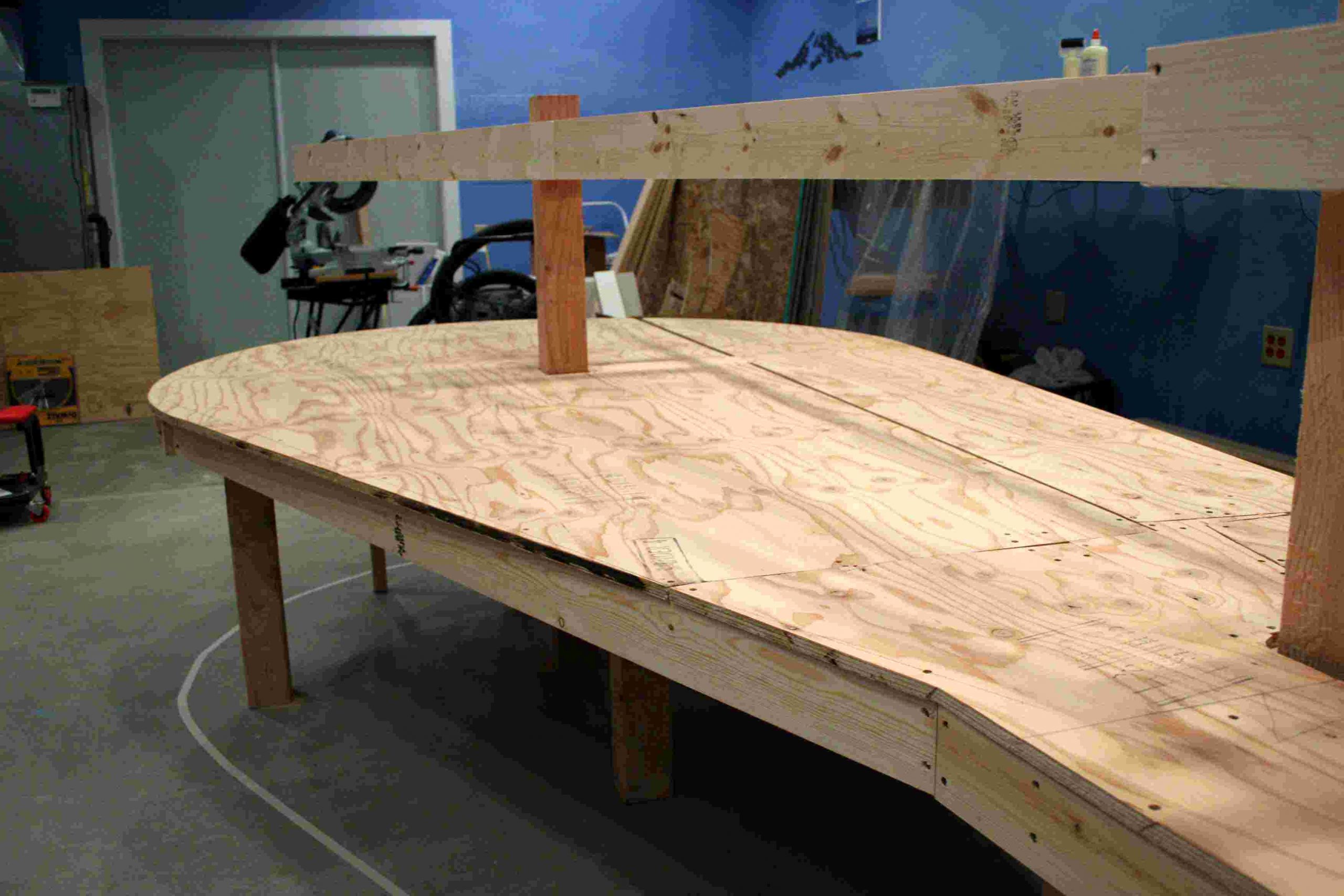
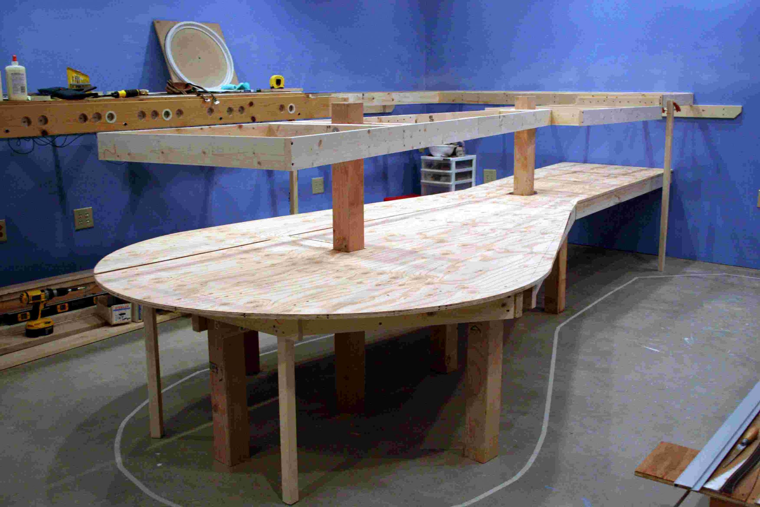
Our first picture gives you a close view of the box construction of the southwest corner tables. You will note that the table that connects the finger to the wall unit is at a different height. This is to accommodate the height of the cross members we will use in the L-girder process. You can also see that we have attached the lower staging yard table to the west wall.
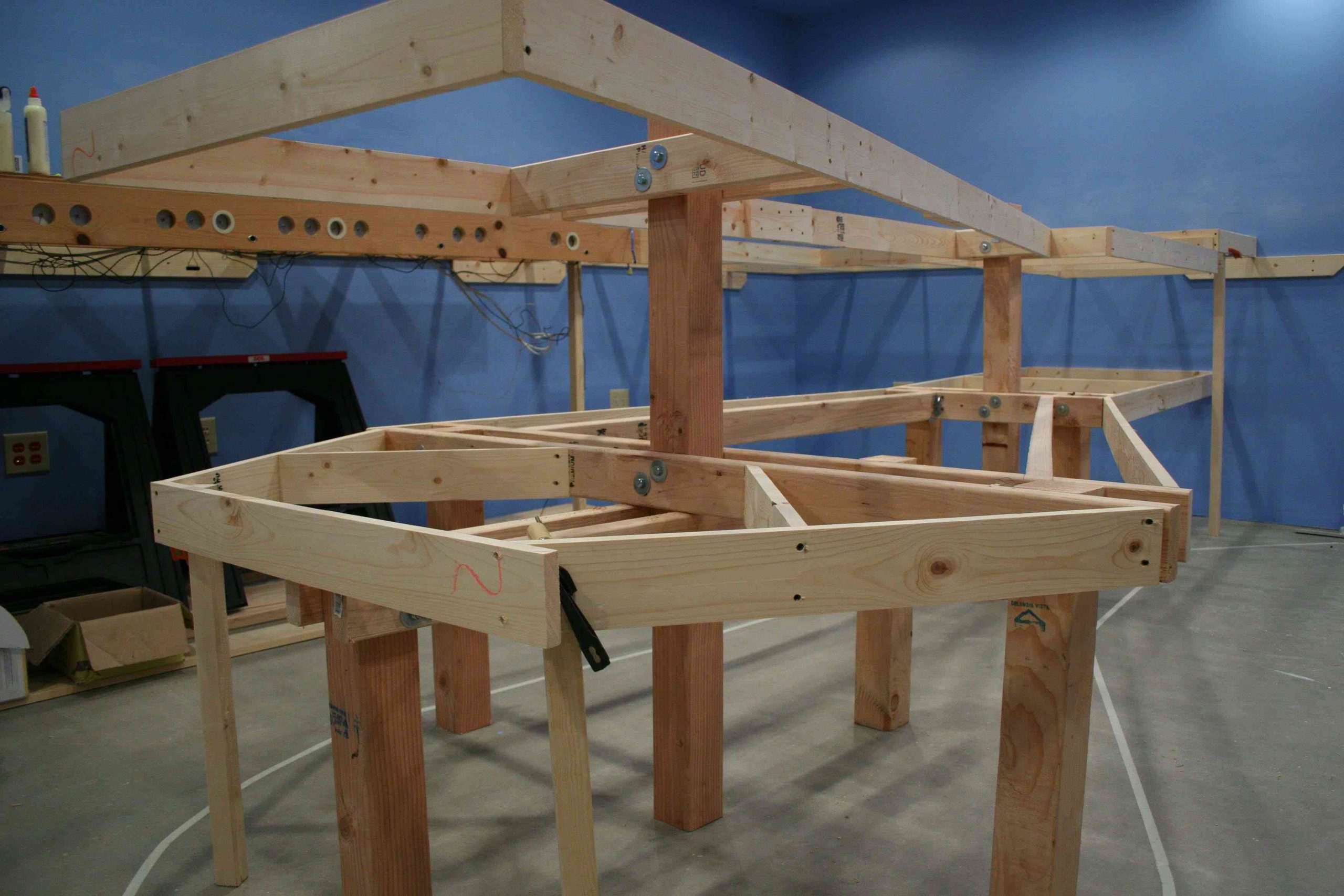
The second view is designed to give you a better look at the staging table. We have attached temporary legs to hold up the outer edge so that we can put weight on the table when we attach the plywood base. Ultimately we will place the legs where they are best fit.
Our first picture gives you a close view of the box construction of the southwest corner tables. You will note that the table that connects the finger to the wall unit is at a different height. This is to accommodate the height of the cross members we will use in the L-girder process. You can also see that we have attached the lower staging yard table to the west wall.
The second view is designed to give you a better look at the staging table. We have attached temporary legs to hold up the outer edge so that we can put weight on the table when we attach the plywood base. Ultimately we will place the legs where they are best fit.
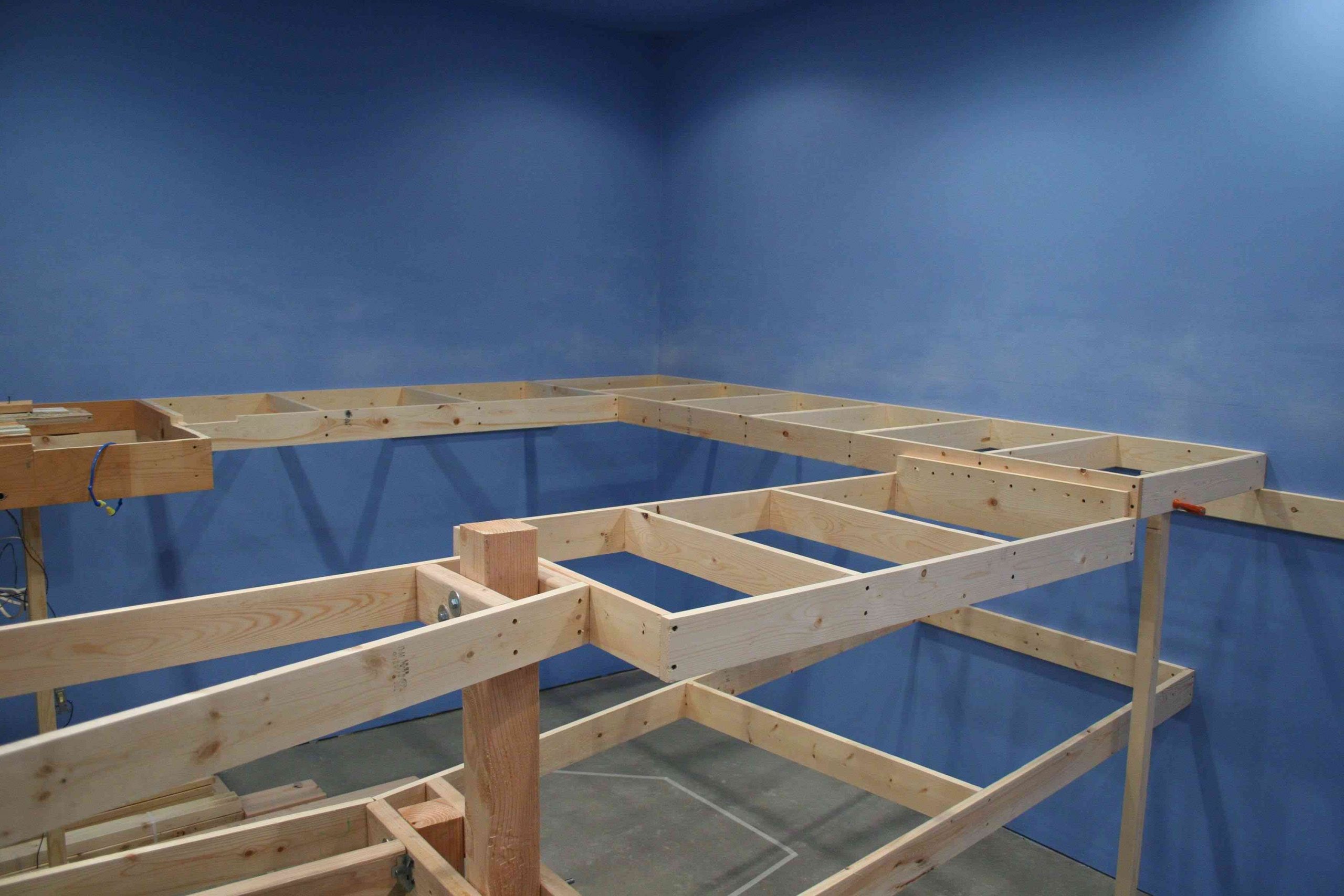
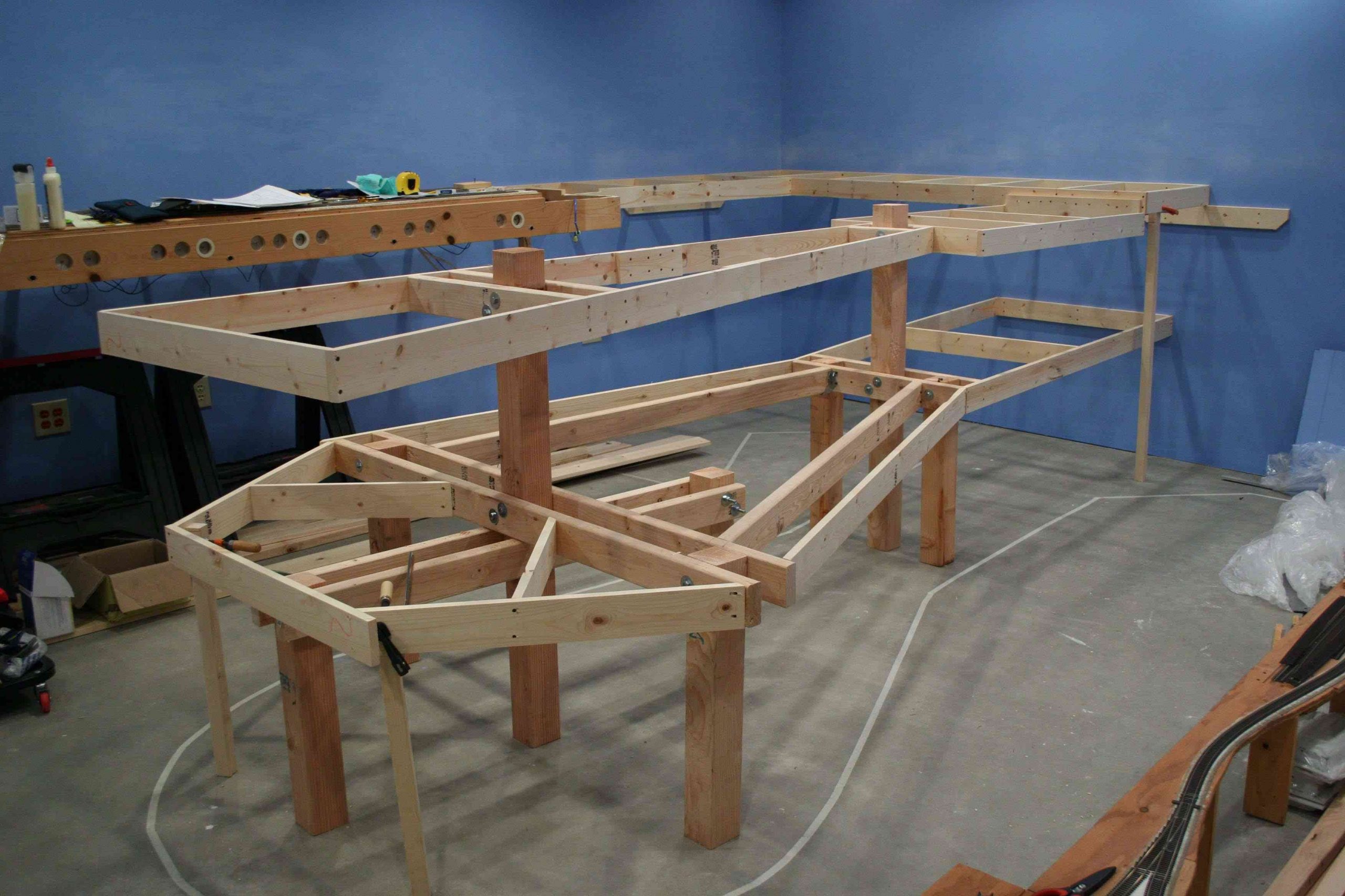
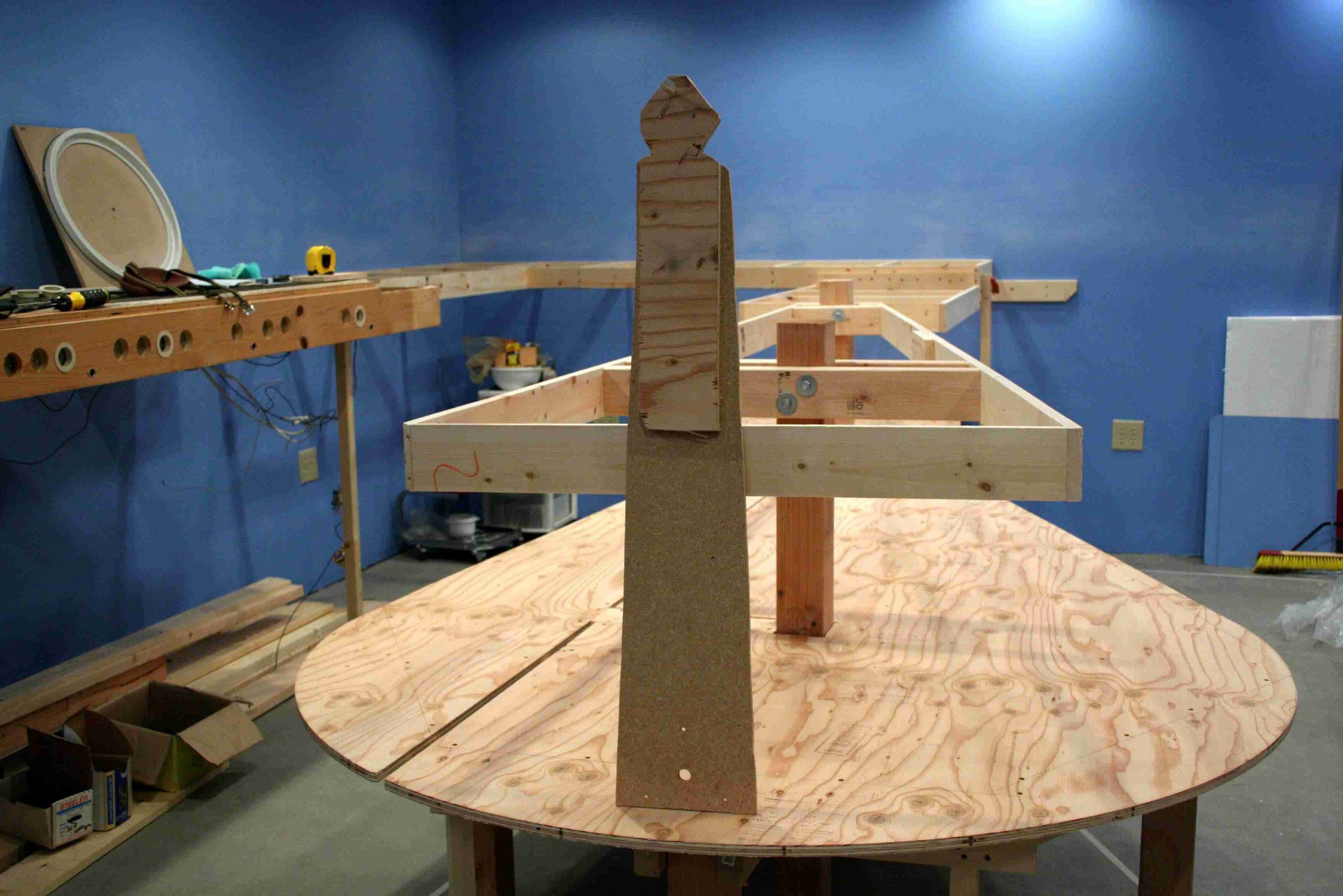
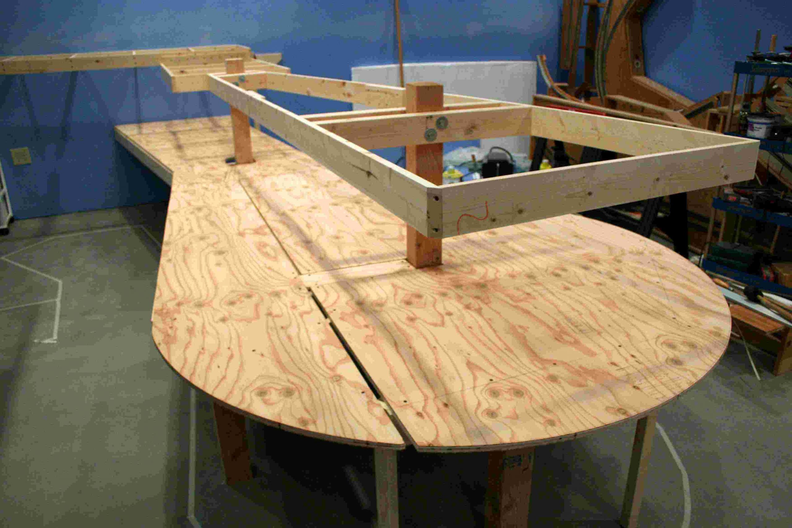
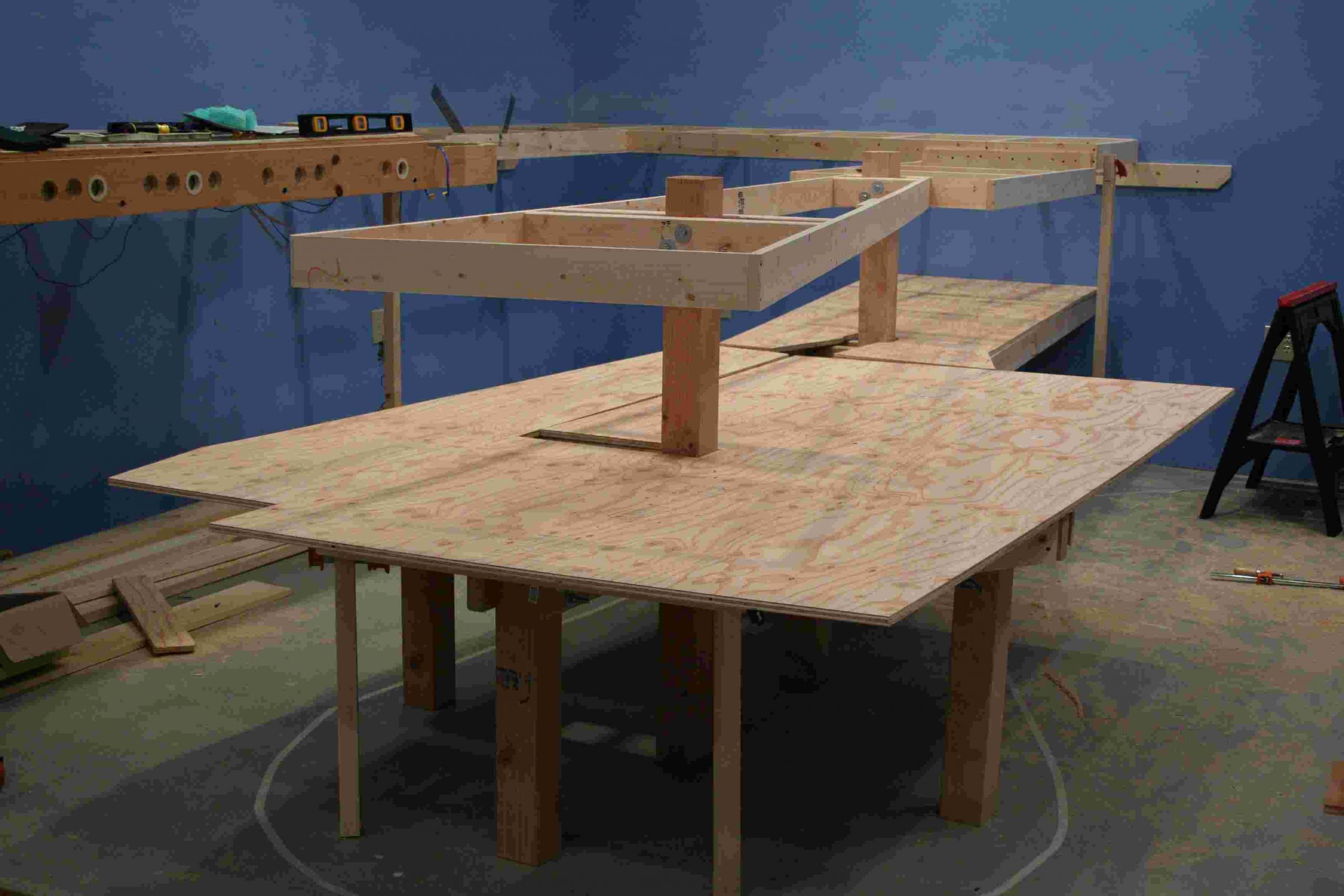
The third and fourth views give you the same basic look, only from different angles. You might also wonder why we have elected to angle the upper table back to where it attaches at its western most location. We chose to do this because our main track is descending below the table and we need as much clearance as we can to ensure nothing impedes that tracks descent.
The final view shows how we are going to lay out the staging table. Our intent is to have a six track staging yard and a complete reversing loop at this level. This level is at 26 inches above the floor and the track will circumnavigate the entire railroad. You can review the staging level here.
Our next step will be to attach the plywood base and to cut the outer radius where we will eventually hang our fascia board. Once the plywood is attached, we will put down a homasote base and the track.
January 2006 (2)
The weekend of January 21, we put our mind to completing the plywood base of the southwest finger table staging level. Originally we had in mind a hexagonal table section, but in the final analysis, a radius curve looks better and is more functional.
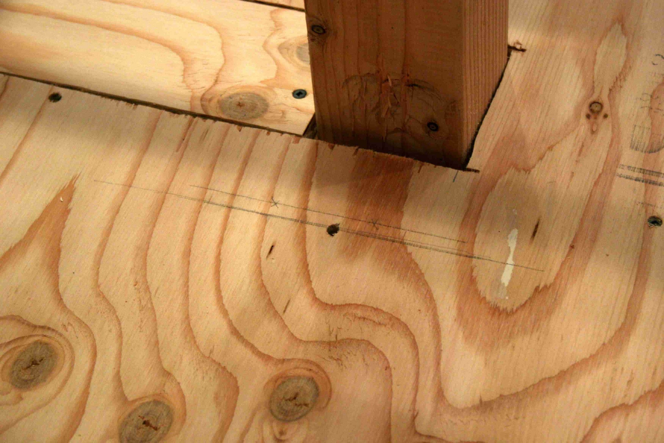
We quickly determined to use a method we have seen several times on the New Yankee Workshop. The method involves use of a jig that holds a router and pivots on a 1/4′ dowel at the center point of the radius. First step, is to find the center of the curve. While there was a bit of trial and error, it all starts with measuring the two points of the curve that are furthest apart. This distance was 66 inches, giving us a 33 inch radius. We then marked that point on the plywood top and made a second measurement from the front edge of the table 33 inches back.
We then had to build the jig. We used 3/8″ press board and 5/8″ plywood to build the jig. You might ask why those two products, simple, they were scraps laying on the floor. The press board spanned the 33 inches we needed and the plywood provided some extra strength. You attach the router by removing the base plate, then marking and drilling holes in the jig. Be sure to recess the screws so there is a smooth base in all cases. We attached the router, plunged the 5/8″ straight cutting bit through the base and then measured back 33 inches to find the center point.
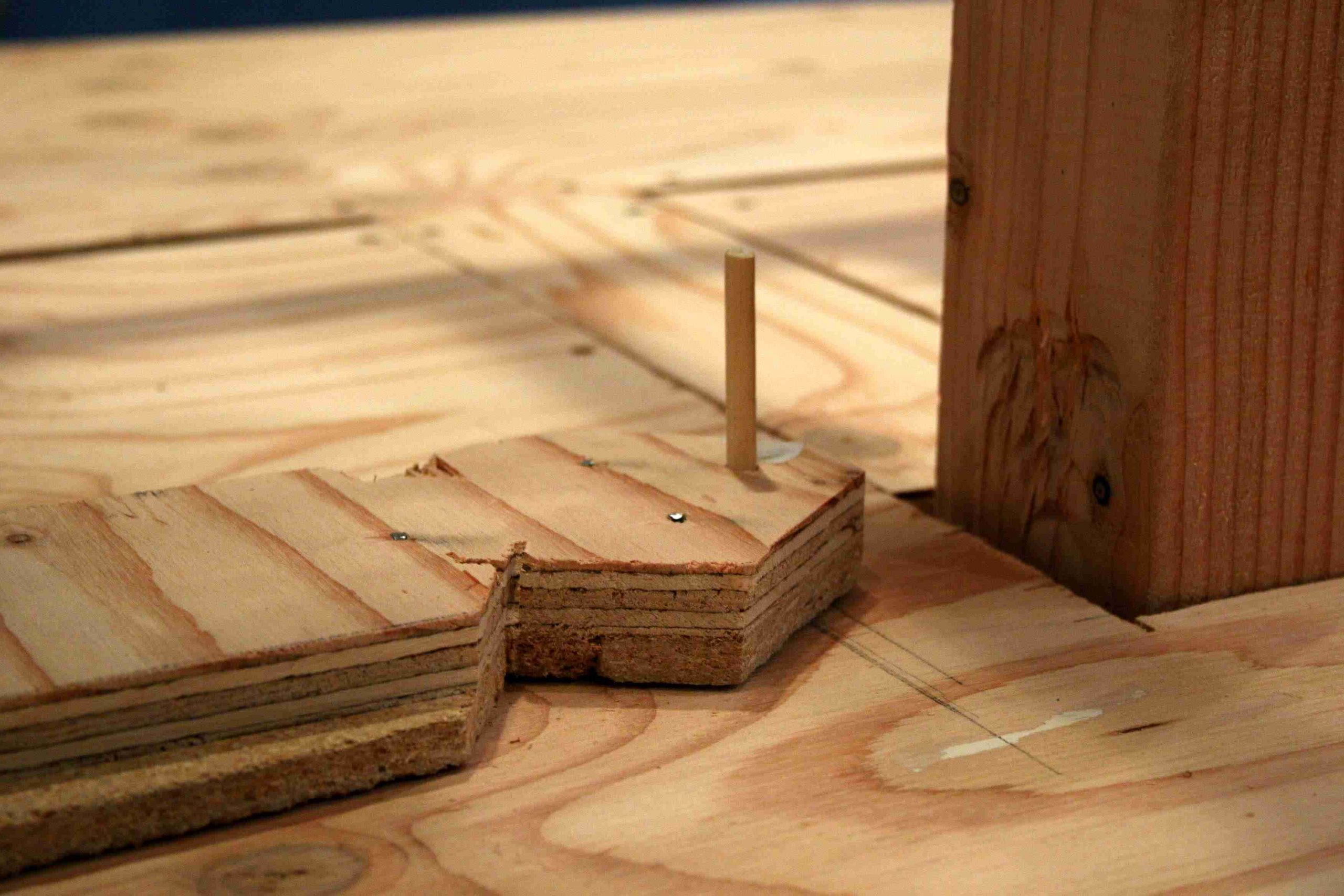
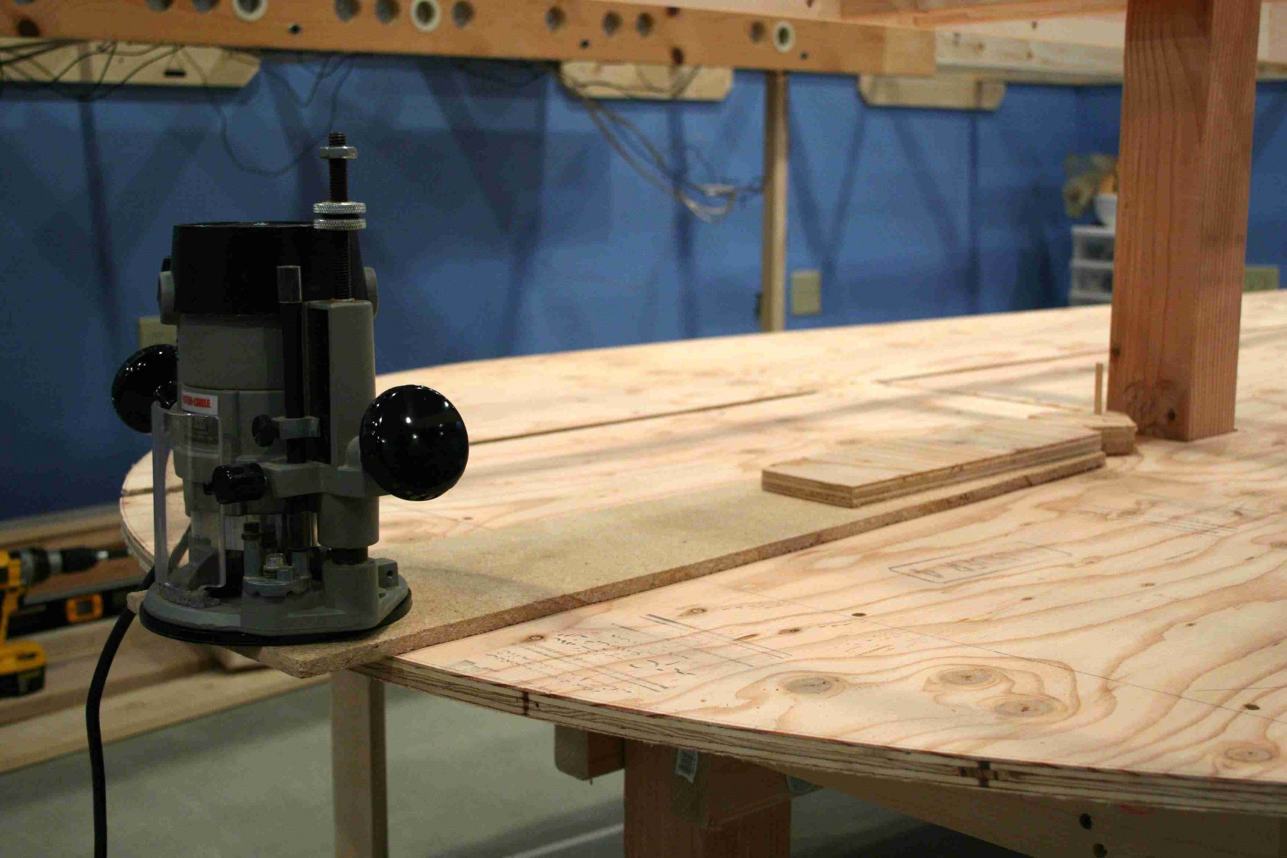
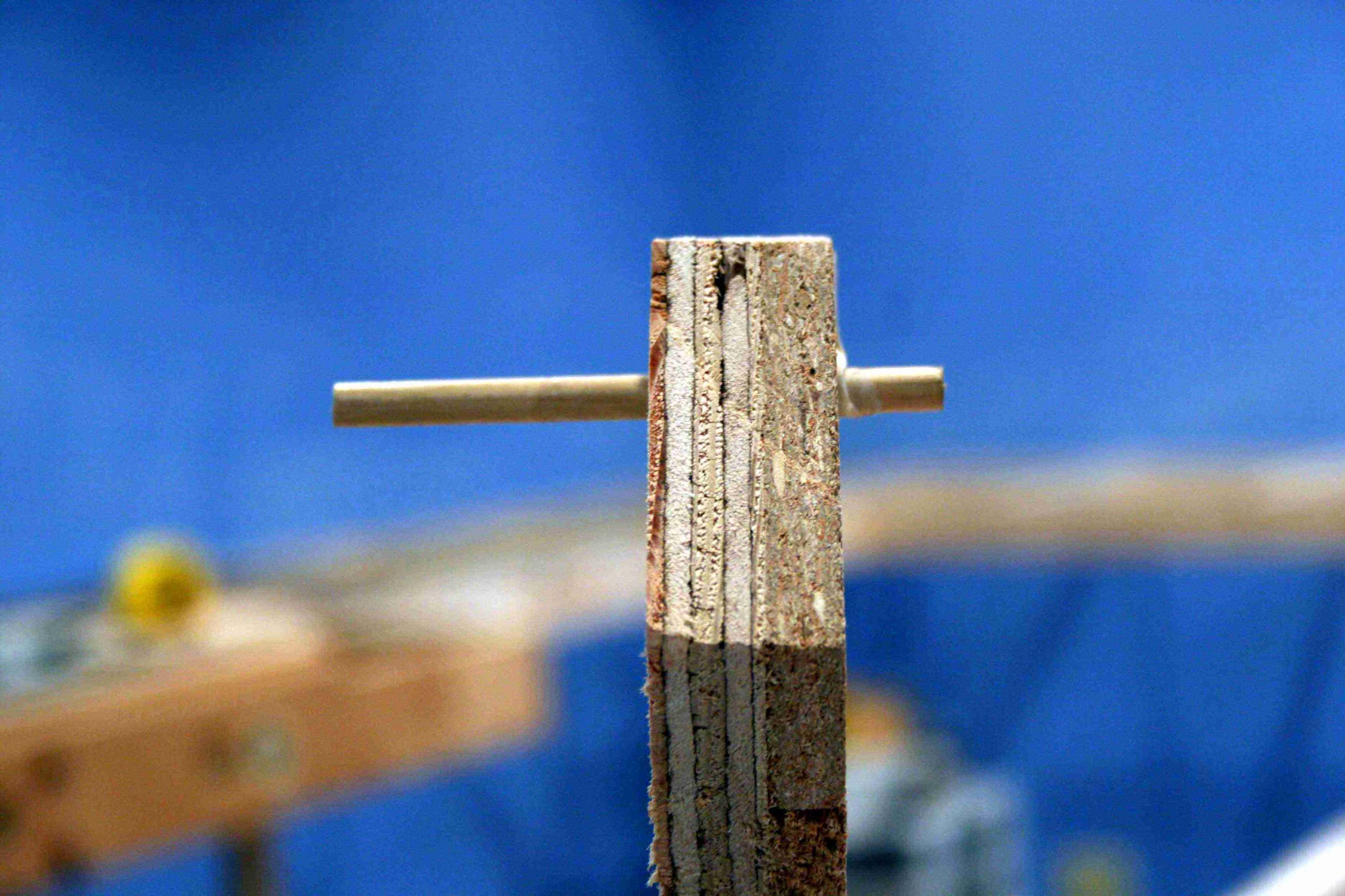
Once built, we drilled 1/4″ holes in the jig and the table top to form the pivot point. We then made a test run and we found we had some clearance problems with the 4×4 post. So we notched the jig to allow the extra swing necessary to complete the radius. You will also note that we used a dremel tool to cut off the excess of the screws used in building the jig, we do this in all cases for safety. Here are the pics that show you how we put this all together (My apologies to Norm Abram for the lack of clean lines on the jig, but it’s functional and that’s all that matters):
Once built, we drilled 1/4″ holes in the jig and the table top to form the pivot point. We then made a test run and we found we had some clearance problems with the 4×4 post. So we notched the jig to allow the extra swing necessary to complete the radius. You will also note that we used a dremel tool to cut off the excess of the screws used in building the jig, we do this in all cases for safety. Here are the pics that show you how we put this all together (My apologies to Norm Abram for the lack of clean lines on the jig, but it’s functional and that’s all that matters):
Here are pics of the final product. You will see we have cut pieces to fill the gaps in all cases except the space that runs the length of the outer table. When we put the main piece in place, we found that a scrap we had from another cut nearly fit perfect. Rather than waste another cut, we decided that once the homosote is laid on top, this small gap will be inconsequential. We placed the outer edge at its best fit, then ran the screws and were set for the cut.
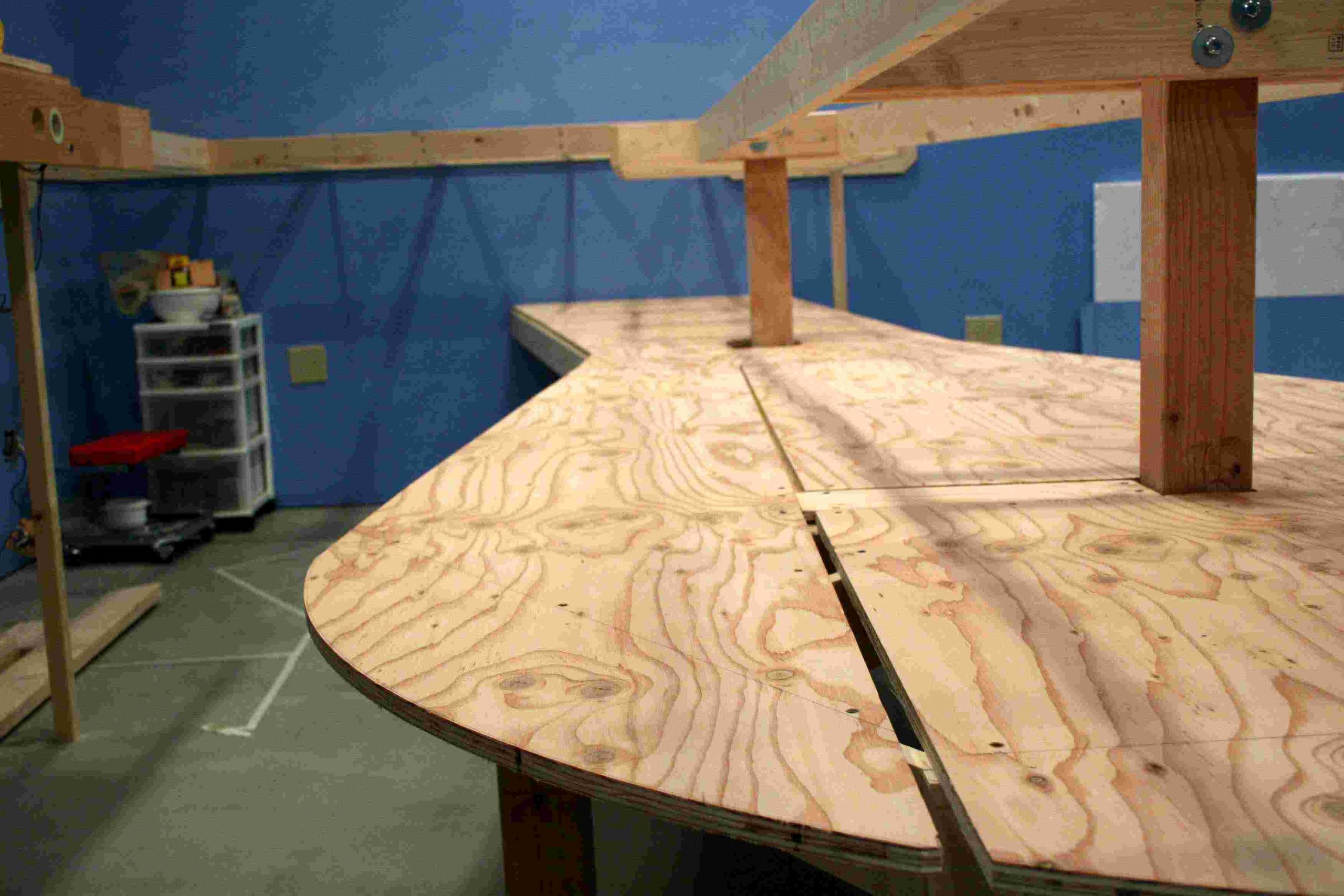
Here are pics of the final product. You will see we have cut pieces to fill the gaps in all cases except the space that runs the length of the outer table. When we put the main piece in place, we found that a scrap we had from another cut nearly fit perfect. Rather than waste another cut, we decided that once the homosote is laid on top, this small gap will be inconsequential. We placed the outer edge at its best fit, then ran the screws and were set for the cut.
April 2006
For the last couple of months, progress was slowed as we felt it was time to salvage as much of the usable track, switches, switch machines and electrical from the old layout. This was a chore that was not anticipated and frankly a bit sad, as it was hoped many of the former layout sections would be used intact. This was not to be. The new layout design made it more practical to salvage what we could, create more working space in the train room and move on.
In early April, we realized that the best time to paint the backdrop on the four walls was now, before we put up more benchwork and succeeded in creating obstacles for ourselves. In order to get this going, research and photographs were the order of the day. Once we had reference photos and made our trips to the art supply store for the acrylic paints, we brought in a projector and cast the digital shots on the wall to outline the various mountain ranges in our region. One modeling tip, use very light touch when tracing the photos, this will leave a light pencil mark to cover when painting. A dark pencil line will be harder to cover with thinned acrylic paint.
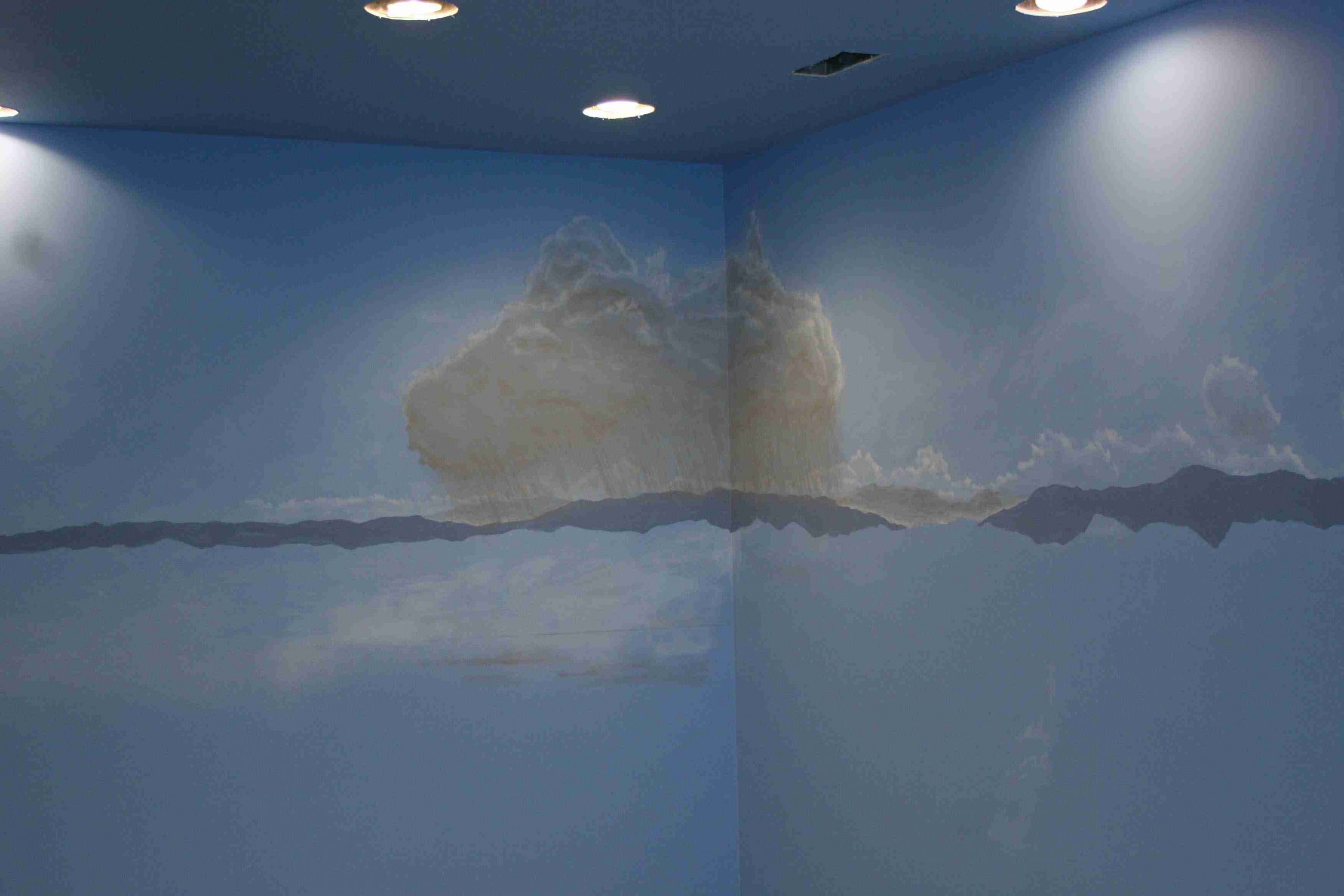
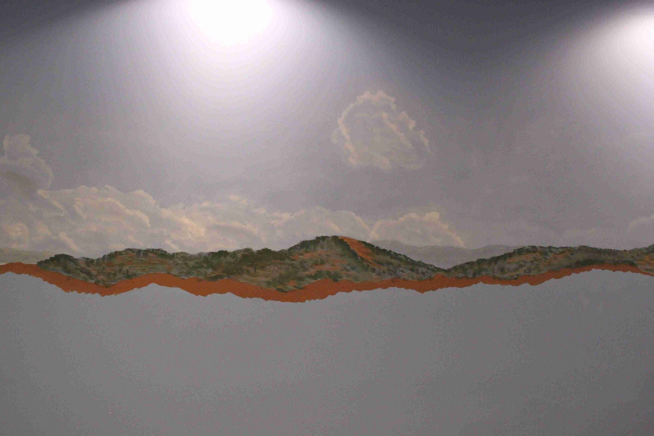
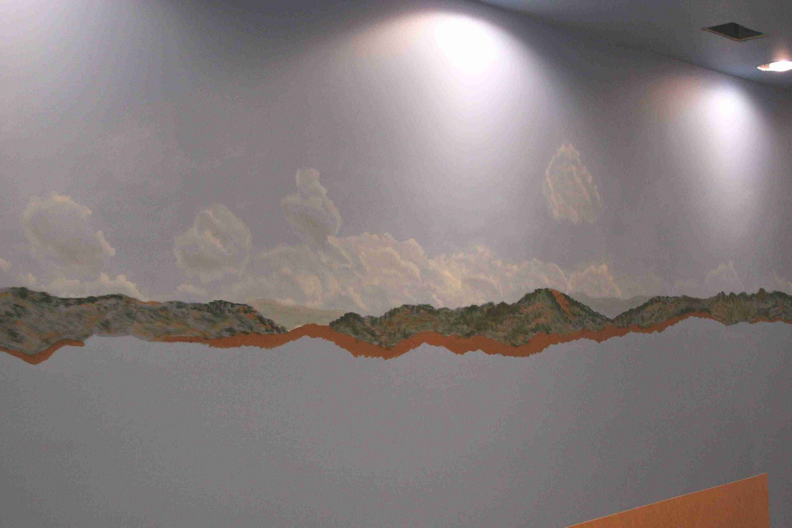
To best understand what you’re looking at; first, all of the walls are painted Rodda Hidden Lake Blue, to represent “sky blue”. Imagine you’re looking straight up outside, this is the blue we are simulating. As your eye comes closer to the horizon, more and more white is introduced. If you don’t believe it, go outside and LOOK! You can see the penciled on horizon lines on the wall. Then, we painted the clouds that are furthest from view. These are represented by the wispy white areas painted by brush, using a dry-brush technique. This means paint is picked up on the bristles and then wiped on the pan or rag until it’s nearly dried off then applied to the wall with a scrubbing motion to give a hazy or misty white background at the horizon graduating to blue as you “look up.”
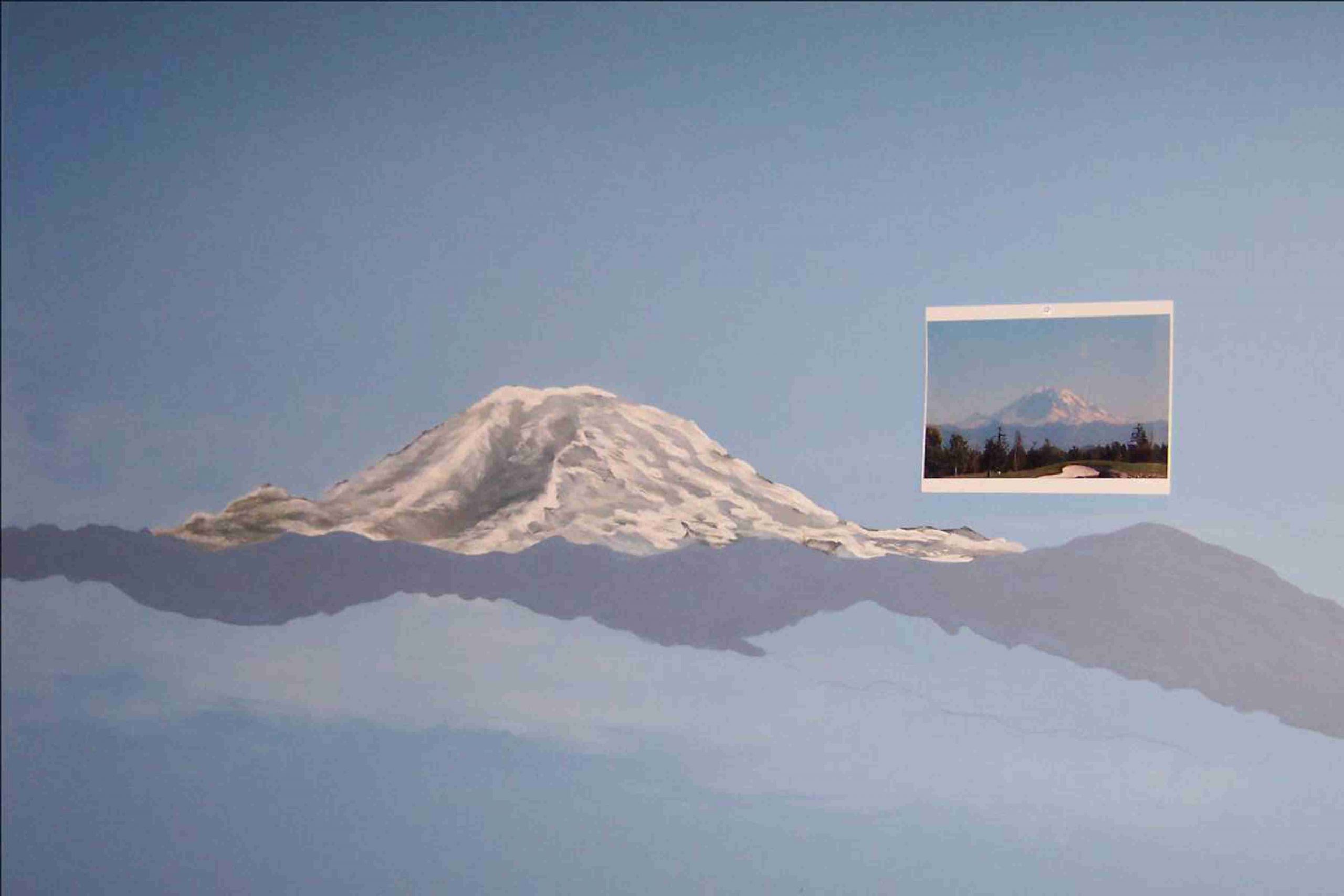
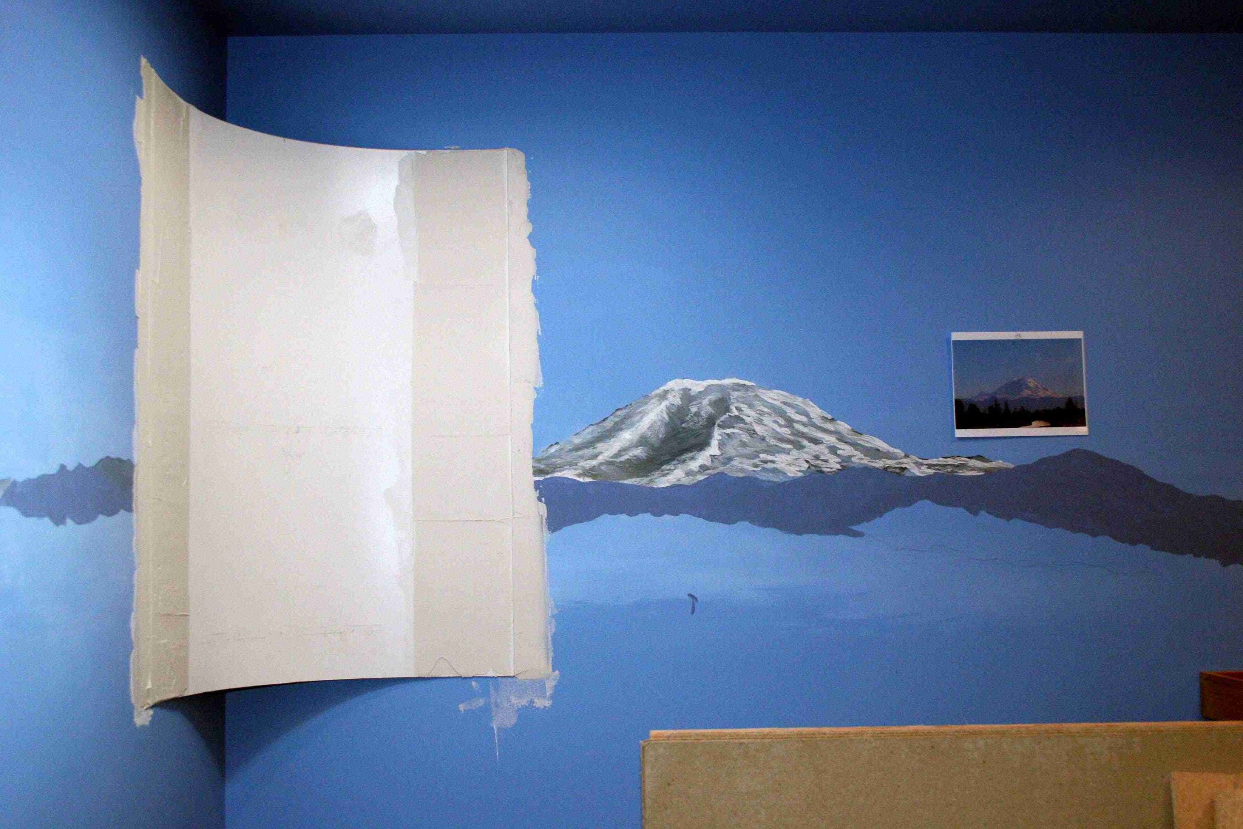
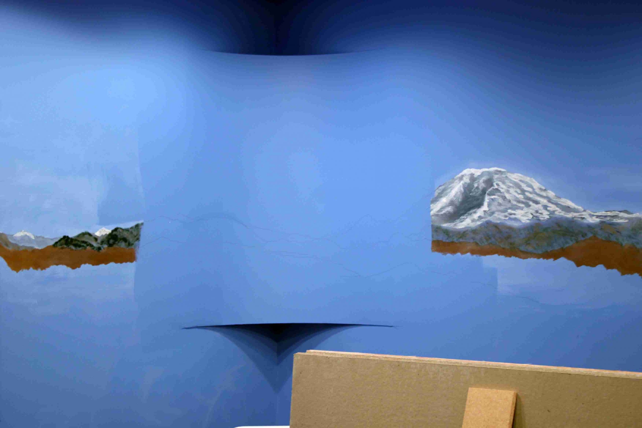
On top of this haze, the mountains are introduced, the furthest away represented by the Slate Gray, again applied by brush. Then, horizon clouds were added using an airbrush. Clouds were added using cloud masks and the next closest mountains were added by brush using a purple-blue color. Look at the picture below with both the painted mountains, specifically Mt. Rainier and the photo we used as reference to see why we chose the color variations.
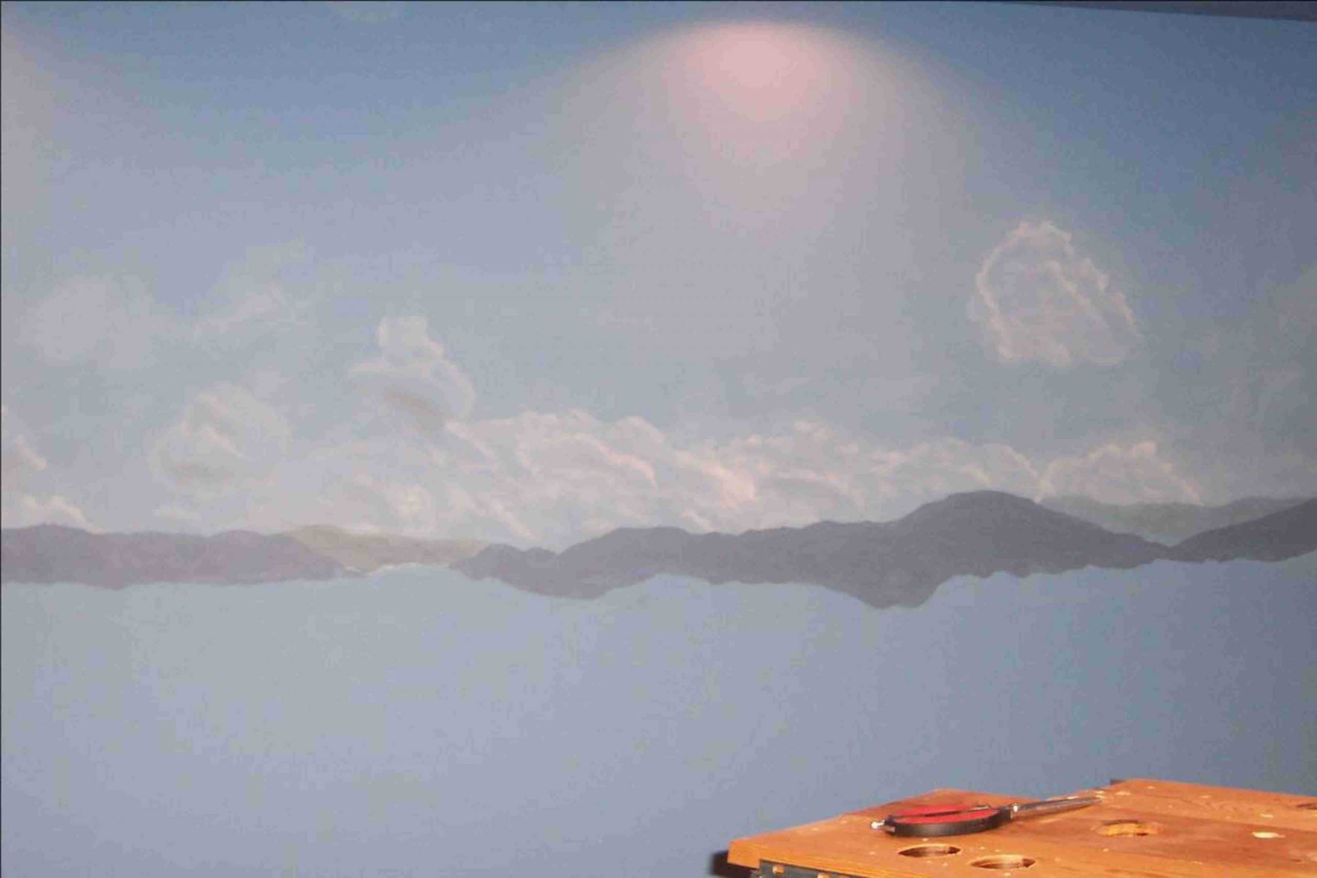
On top of this haze, the mountains are introduced, the furthest away represented by the Slate Gray, again applied by brush. Then, horizon clouds were added using an airbrush. Clouds were added using cloud masks and the next closest mountains were added by brush using a purple-blue color. Look at the picture below with both the painted mountains, specifically Mt. Rainier and the photo we used as reference to see why we chose the color variations.
All of the work you see is a “first try”. Needless to say that first time jitters were the order of the day and much time was spent debating each step. After completing this phase, we realized that it’s much easier than anticipated. The most important thing is not to rush to judgment about the work in progress. Step back and evaluate your work frequently.
The rendition of Mt. Rainier, was a four step process. First, gathering the photos, specifically the one you see tacked to the wall in the picture below. The second was the projection of the photo on the wall for dimensioning. The third step was the base coat, which included darker colors like reds, tans and slate blue. The final step was to add the snow and work the contours of the mountain in using the same dry brush technique described above. The next and last step will be to complete the highlights in the purple region, then to add the next closest mountain range. This layer will show browns, greens and relief such as trees, rocks or far away buildings. Lastly, large trees may be painted over all layers to give a sense of depth and closeness. Then, we graduate into the “real” physical scenery applied near the walls and outward to the layout edge.
October 2006
As you will recall from the April update, we decided to salvage the old layout. We also made the determination, “Tis better to paint backdrop before benchwork installed, than to break one’s back leaning over the benchwork after. (Or for you in Gila Bend, AZ, paint the backdrop first, stupid!).” Profound, I know, but none-the-less, a pioneering breakthrough in backdrop methodology. Well once we started the painting, we found that it wasn’t that hard, heck most of us learned painting in kindergarten, this is just an advanced version thereof. To be sure, we revisited our guru, Bill Alexander, “isn’t that beautiful, just fire it in there!”, but in all, it went much better than anticipated. We had only one complaint, the corners had too much shadow. The only cure, coved corners. So for those of you who have been questioning our progress, this is what we have been up to.
The coving process was started by cutting out curved forms from plywood stock. We the affixed the forms to the corners with 2×2 supports. To form the corners, we used 1/8″ masonite with one side finished for texture. It was determined early on (stroke of luck), that we could insert a PVC pipe within the confines of the forms that would enable us to run conduit up the wall to eventually provide us with a location for blue floodlights for night running during operating sessions. You will note the pipe in the pictures below. We will describe the floodlights in more detail another time. We then cut the masonite to length and used construction adhesive to adhere it to the forms, with a bead of adhesive down each vertical side to ensure lack of movement. Temporary screws held it in place until dry.
Now that all took about a day. What transpired next took weeks.
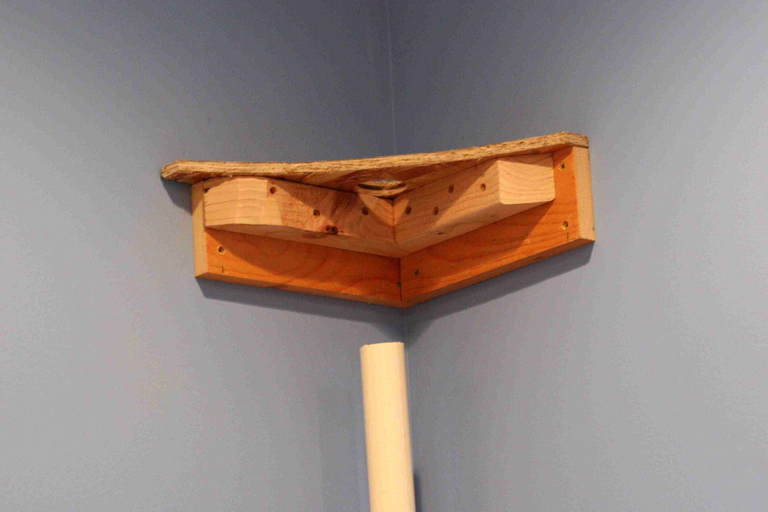
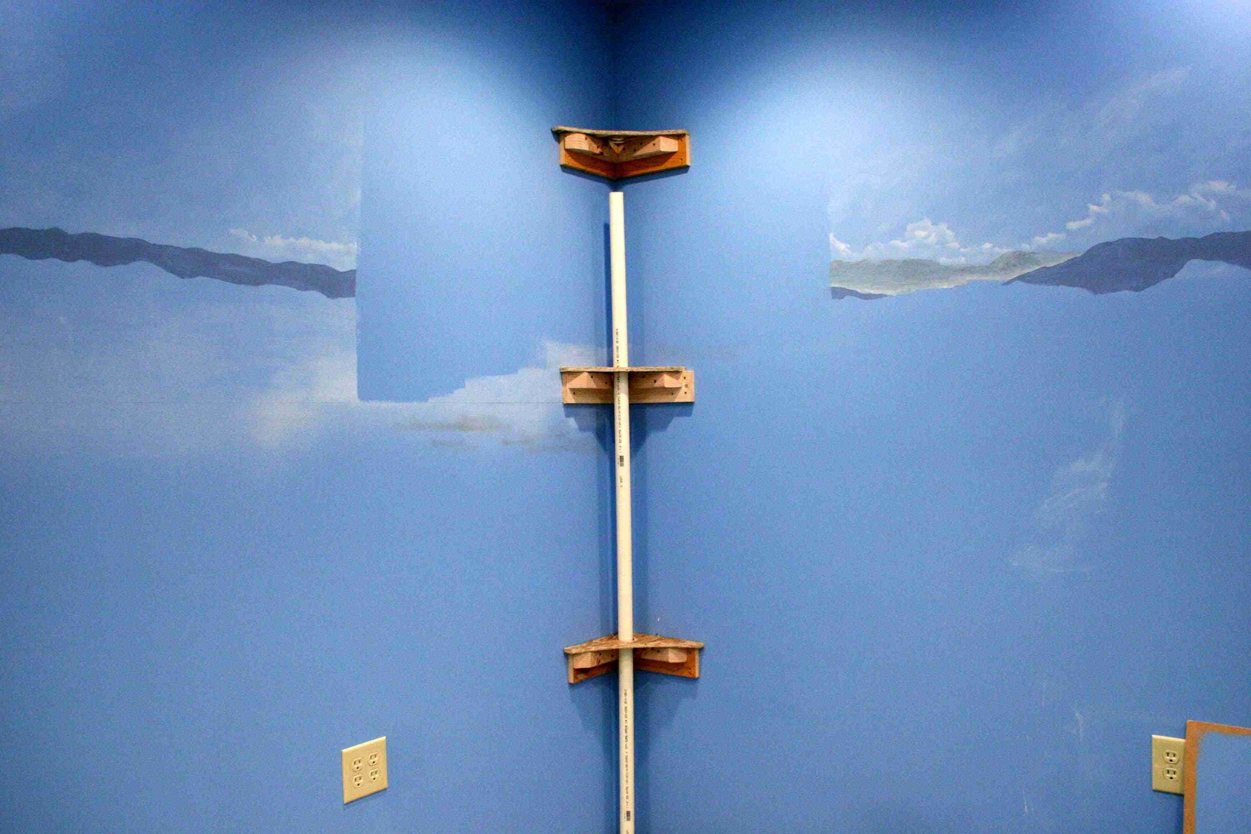
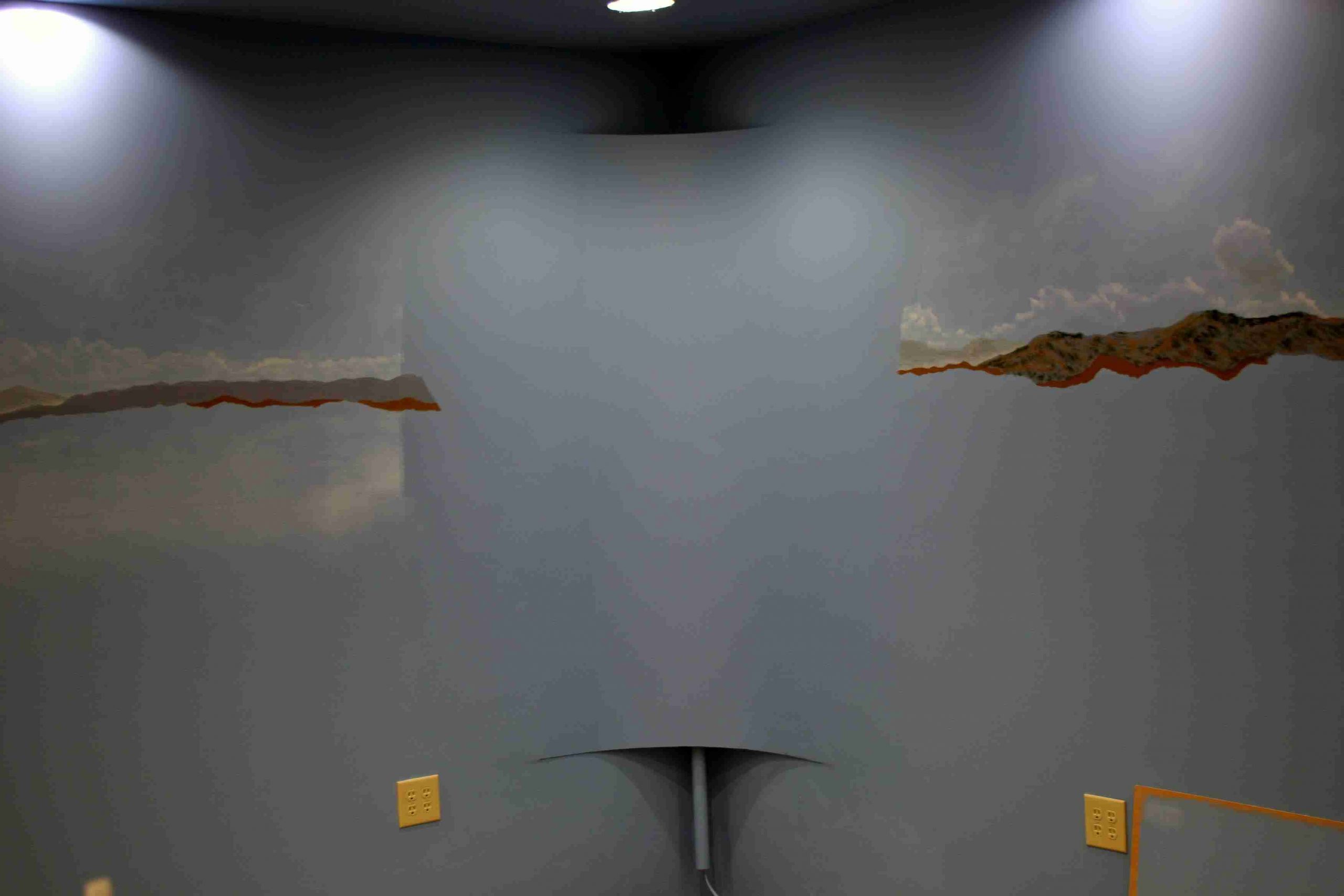
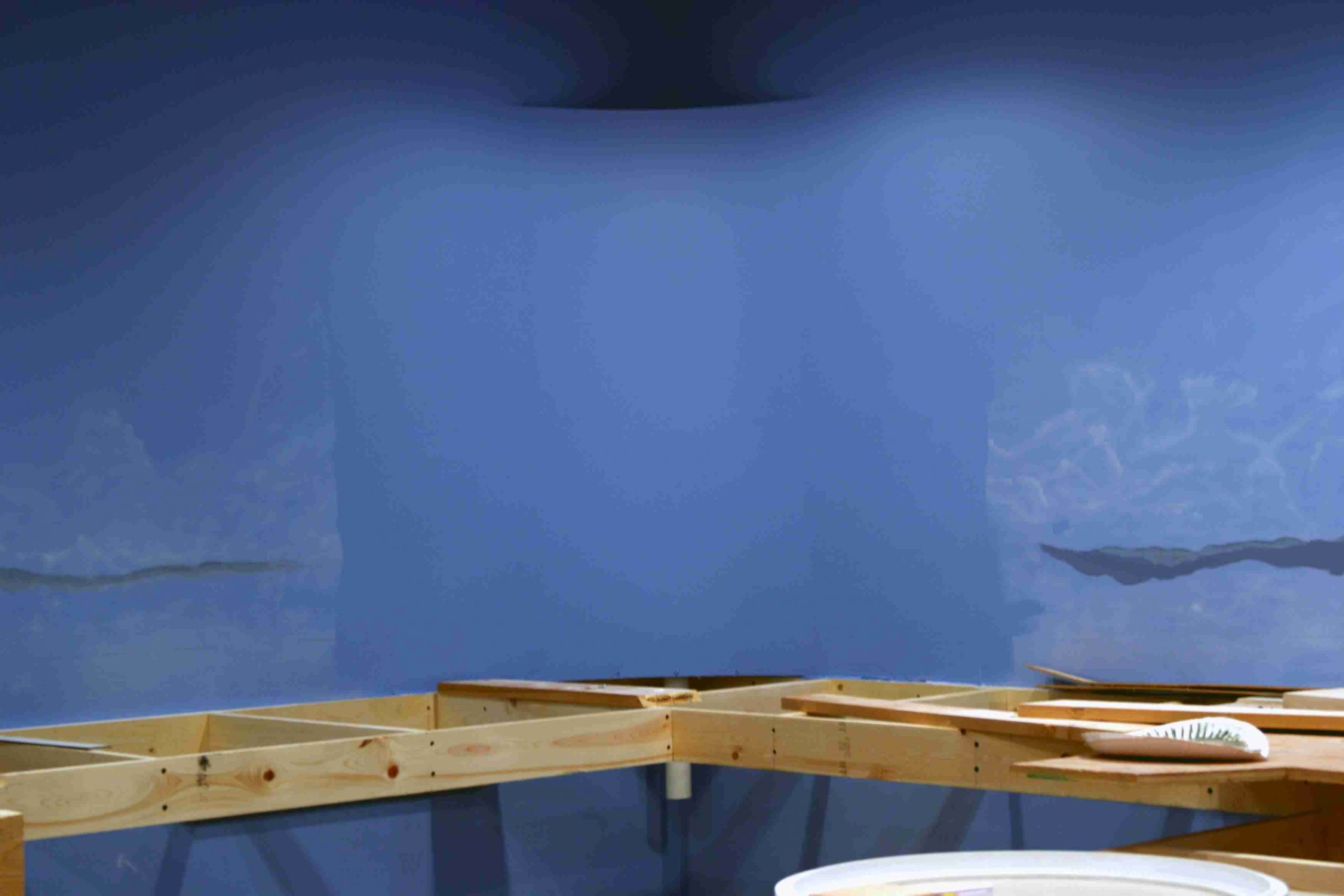
To say that painting backdrop is difficult is one thing, but I say it doesn’t hold a candle to drywall mud. Frankly, if there were an easier way to have done this, (aka hire it out), I would have in a second, problem is I was too stubborn once we started. Coat after miserable coat of mud to ensure smooth edges and an equally smooth transition to the wall behind, kept this phase alive for months. But, as you can see from the pics below, we have finally finished the drywall portion and repainted the wall the base blue, so that we can complete the backdrop painting. There are also some extra pics of our backdrop status.
To say that painting backdrop is difficult is one thing, but I say it doesn’t hold a candle to drywall mud. Frankly, if there were an easier way to have done this, (aka hire it out), I would have in a second, problem is I was too stubborn once we started. Coat after miserable coat of mud to ensure smooth edges and an equally smooth transition to the wall behind, kept this phase alive for months. But, as you can see from the pics below, we have finally finished the drywall portion and repainted the wall the base blue, so that we can complete the backdrop painting. There are also some extra pics of our backdrop status.