Layout Construction Updates for 2007
The Home and Design of the RGW
February 2007
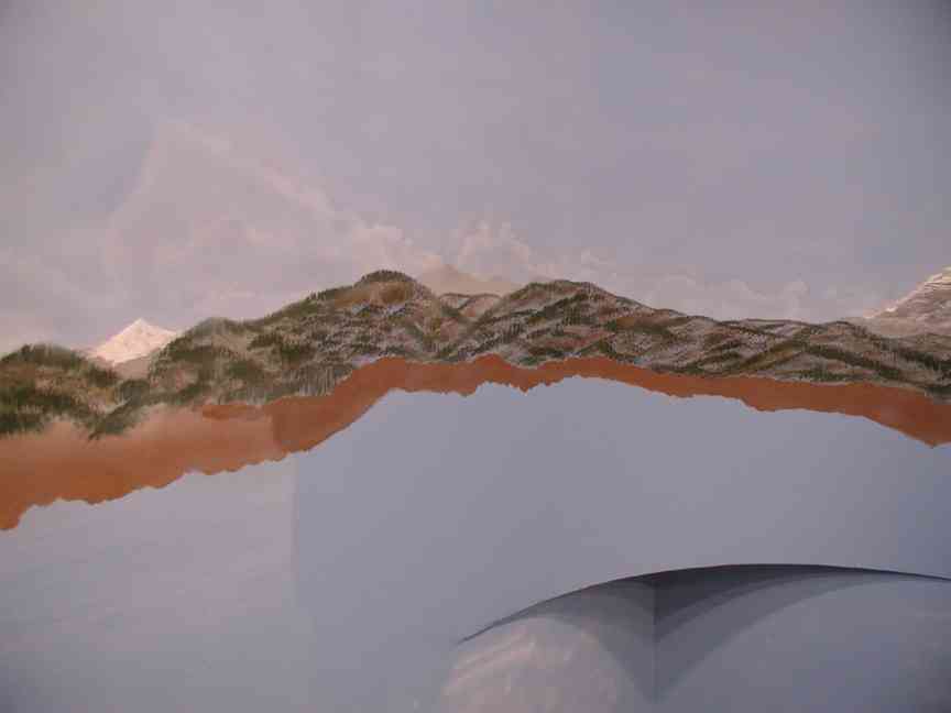
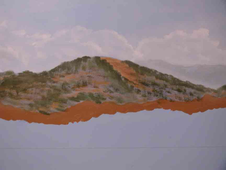
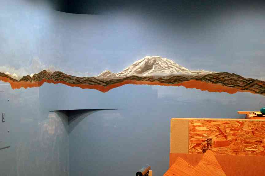
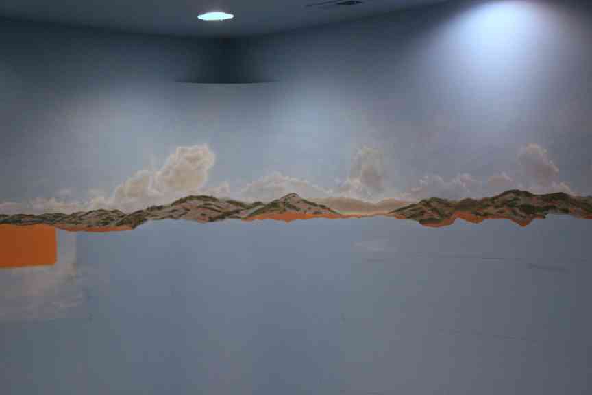
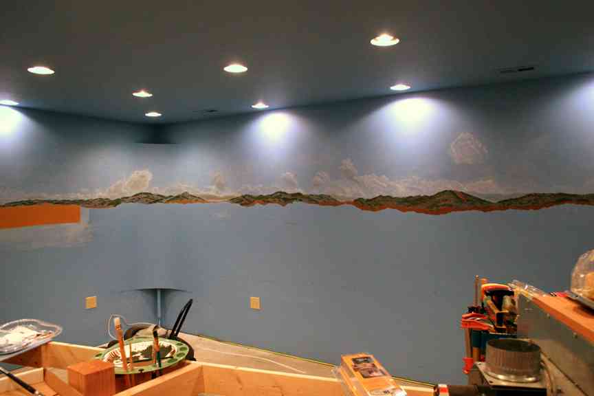
Backdrop painting continued on the perimeter wall of the train room. As of this entry, we have completed as much of the backdrop painting as we feel is necessary to move to the next phase of construction. The painting is a combination of acrylic paints applied by hand using conventional brushes and an airbrush. The acrylic was thinned 50/50 with water for use in the airbrush. A small fan brush was used to dab in the tree tops after the hillsides were painted in with their base color. If you have any questions about the techniques we used, please drop us an email.
As shown in the pictures below, the backdrop covers approximately 300° of the room, with only the extreme NE wall unpainted, as it houses the workbench and cabinetry. While it is anticipated that additional painting will be necessary as we progress with scenery, it “feels” right to move back into construction at this point.
Other activities completed thus far include laying out the location of the NW and N wall table sections, as well as the NW finger table. This was accomplished using a variety of tools, most notably the Cadrail drawing of the layout which provided the coordinates for reference points in the table sections. We used those points to mark the floor and then played connect the dots with a long straight edge and a trammel where curves were required. Once the floor sections were traced on the floor, we laid down masking tape to simulate the front edges of each table. An example of that method can be seen here. By following the practice, we can determine well in advance if we have issues with such things as layout design, spacing and aisle width. Trust me, it’s far better to spend the time playing with masking tape, than to build a table section, only to find you can not maneuver around it.
Other activities completed thus far include laying out the location of the NW and N wall table sections, as well as the NW finger table. This was accomplished using a variety of tools, most notably the Cadrail drawing of the layout which provided the coordinates for reference points in the table sections. We used those points to mark the floor and then played connect the dots with a long straight edge and a trammel where curves were required. Once the floor sections were traced on the floor, we laid down masking tape to simulate the front edges of each table. An example of that method can be seen here. By following the practice, we can determine well in advance if we have issues with such things as layout design, spacing and aisle width. Trust me, it’s far better to spend the time playing with masking tape, than to build a table section, only to find you can not maneuver around it.
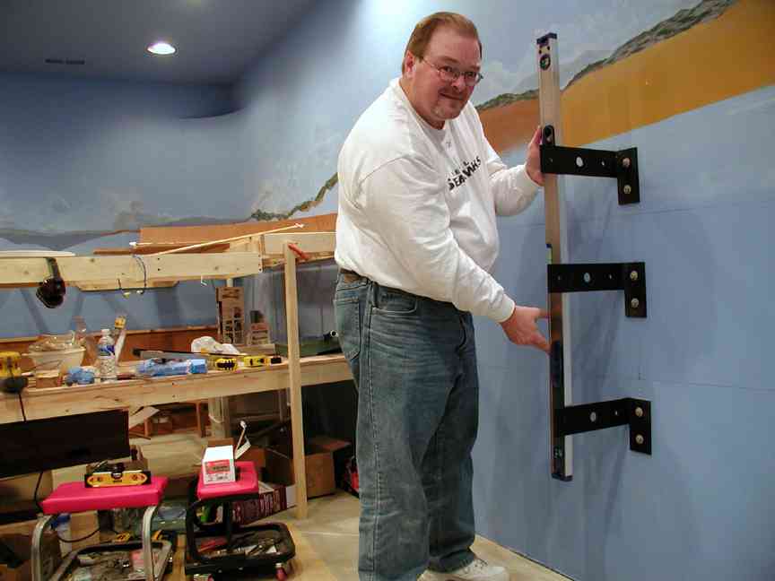
We also reviewed the grades we have assigned in Cadrail and then put them on the wall to get a visual taste of the flow of the track. This gives us a sense of where table sections might need to be adjusted to compensate for risers and it also gives us a quick look at where the track is really headed and where we might want to adjust the grade to ensure track reaches its appropriate destination. In this photo, you can see the grade lines we have placed on the wall.
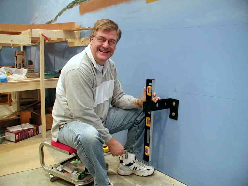
Finally we completed the day by determining where we will mount our hanging brackets for the NW and N wall table sections. Our goal is not to have a single table leg along both of these stretches of the layout. In our next entry, we will detail just how this will all work.
March 2007
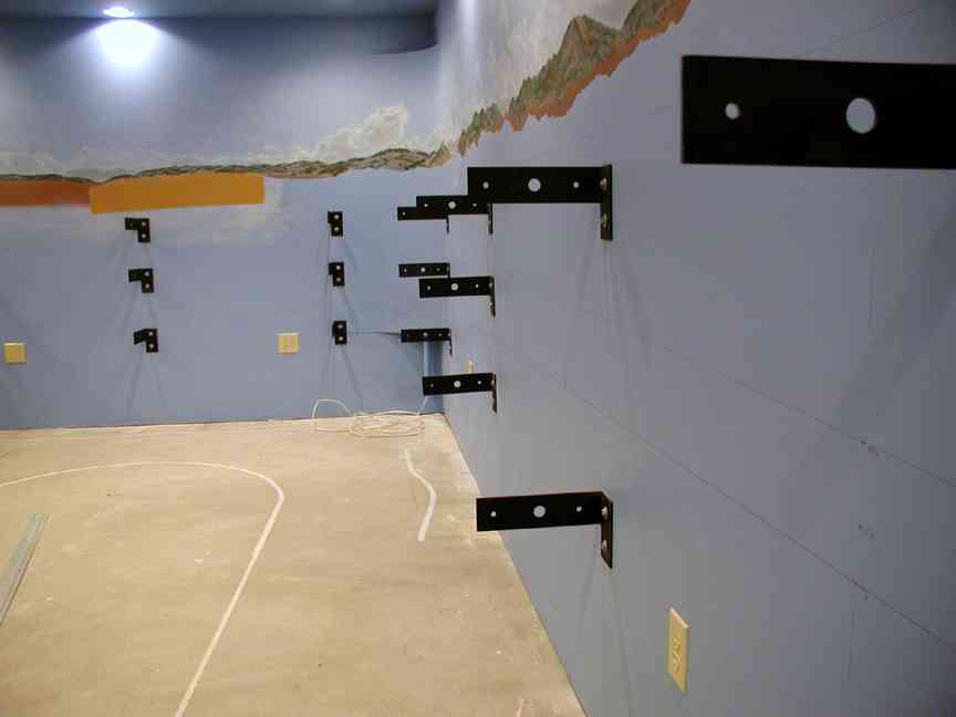
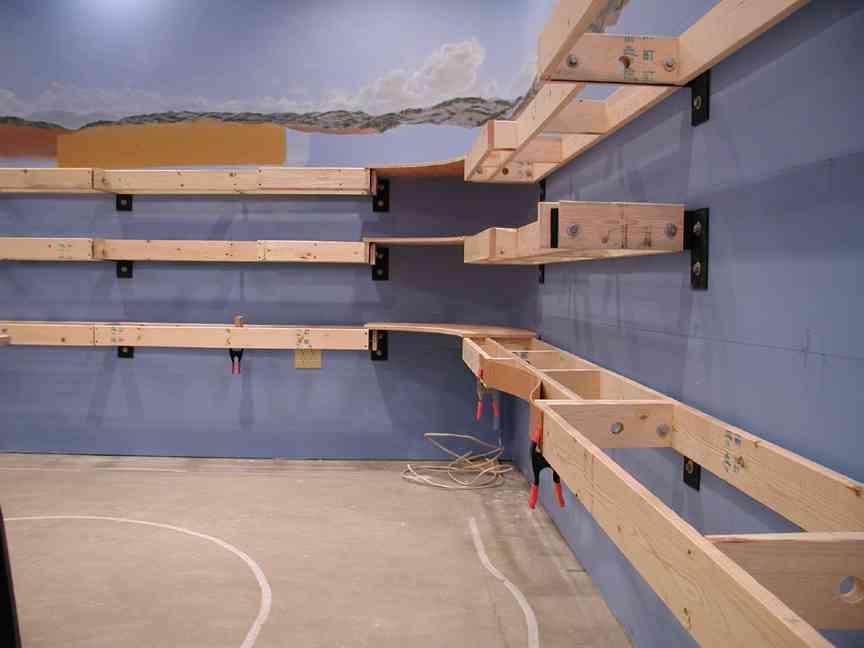
With the backdrop set for now, we set our sights on construction of the northwest and north wall sections of the layout. As we mentioned in the February update, we determined locations of our hanging brackets for the NW and N wall table sections. Our goal is not to have a single table leg along both of these stretches of the layout. The reason for this is a combination of the depth of the table, only a maximum of 1 foot, and the width of the aisle along this section. This combination will put operators and patrons in close proximity to the table edge at all times, as such, the risk of tripping on outer edge table legs is too great.
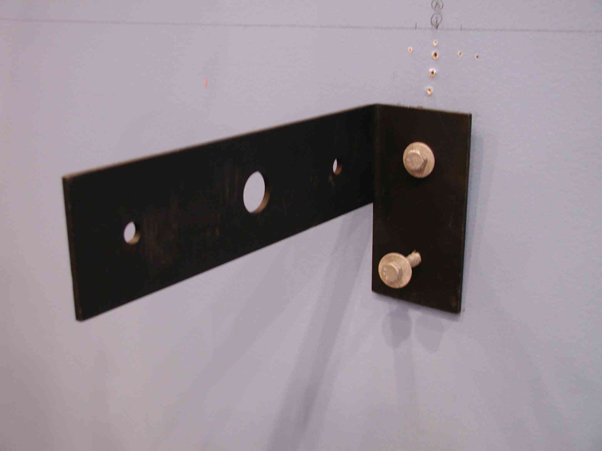
The first concern was how to mount the wall sections without external legs. We considered moving the legs back from the table edge, but that didn’t really address the issue, given the shallow depth of the table. Brackets seemed the only real solution, but then what kind. Angle brackets were considered, but given that three separate levels of track ran through this area, angle brackets would present a visual obstruction that was not acceptable. After sitting with pencil and paper, a concept of our bracket was born. Steel plate, 3″ in width, 11″ long, 3/8″ thick and bent in the shape of an “L”. Four holes with 7/16″ diameter for mounting and one 1″ diameter hole to run conduit through. Fortunately, one of my customers is a metal fabricator and he agreed to make 20 of them for the project.


March 2007 (2)
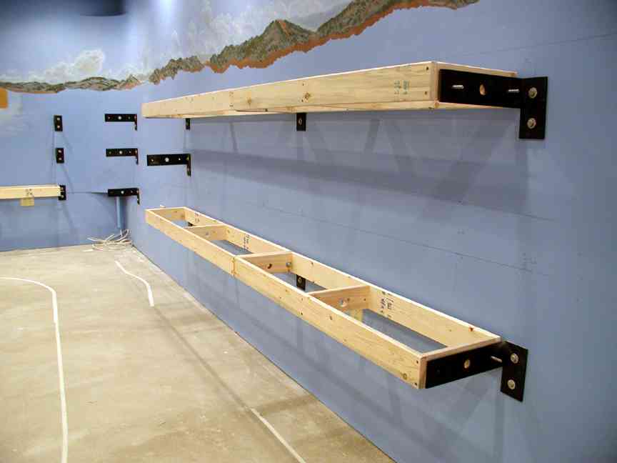
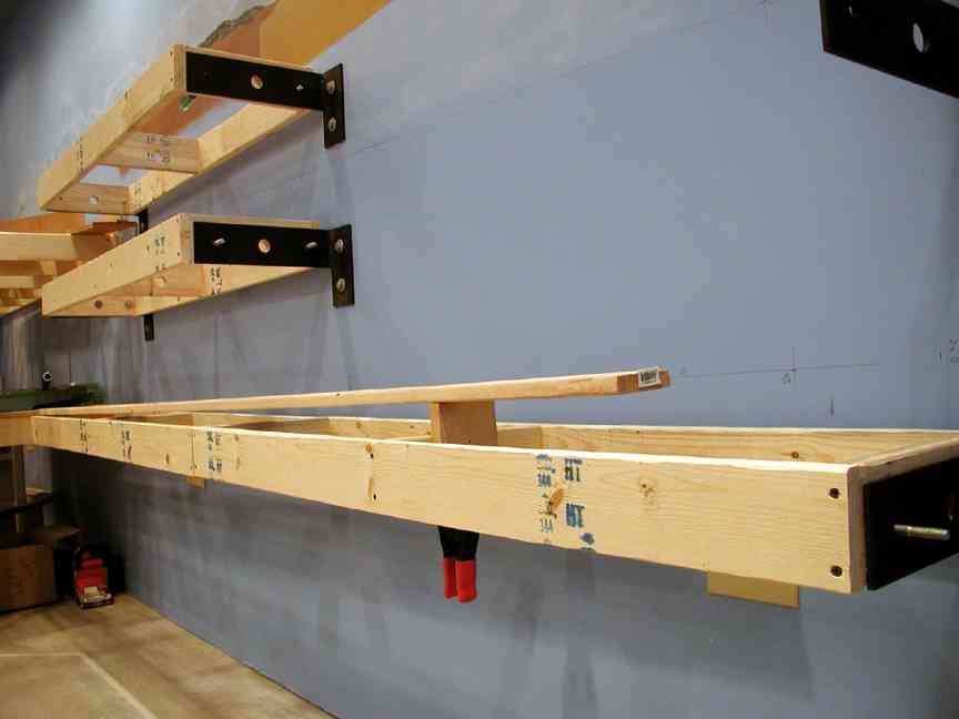
In our next report, we anticipate all of the boxes will be built and installed. That then leads us to our next hurdle, the construction of the “North Blob” as we affectionately refer to it. You can see the drawing here.
April 2007
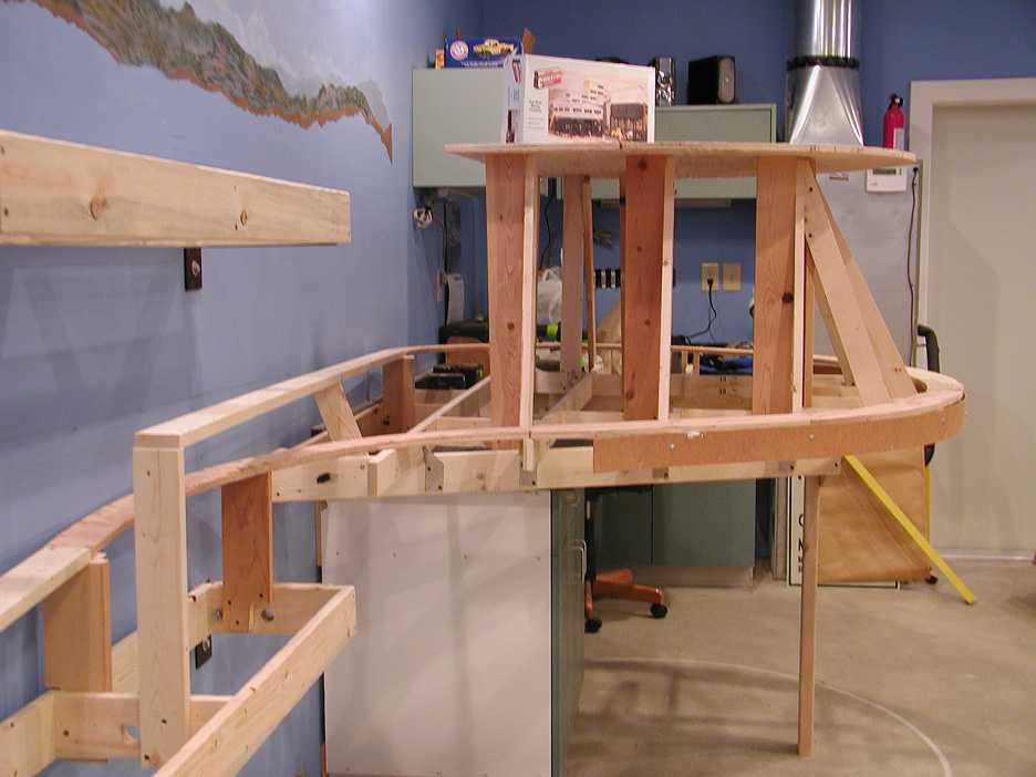
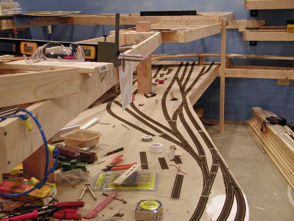
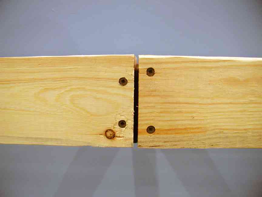
As we touched on in the March report, this work session was devoted to the construction of our “curved” boxes and the NW corner of the layout. As you can see in the three pictures below, we didn’t exactly create a curved box. That would have required us to laminate thin strips of plywood and construct a curved form to tie it all together. Way too much work for this stage of construction. Therefore, we built conventional boxes with a twist. We will ultimately use masonite to form the fascia, so we decided to let the fascia create an illusion of a curved box.
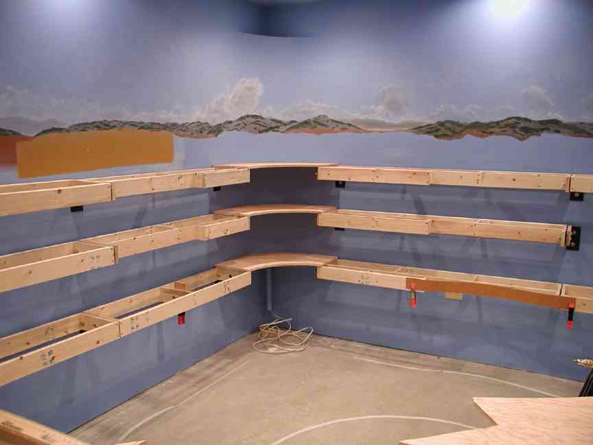
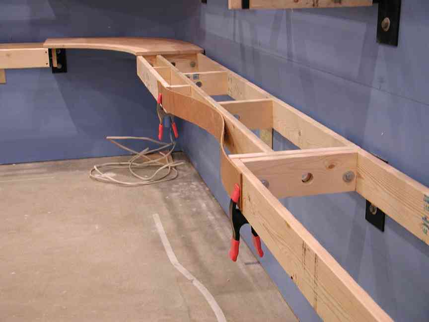
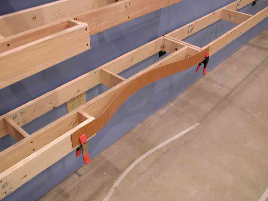
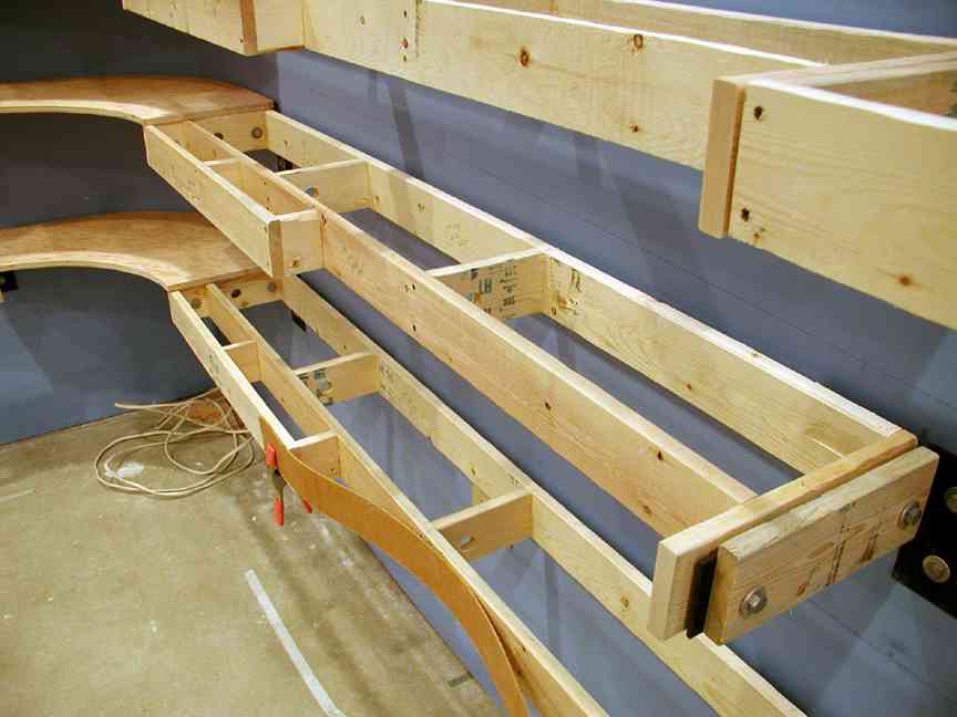
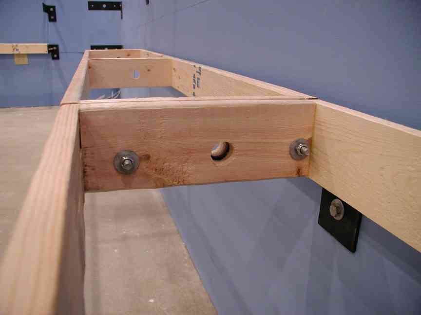
The pictures below provide other views of our finished product. The second picture needs some explanation. When we addressed the issue of constructing special boxes to fit these corner sections, we quickly decided another option was necessary. We came to the conclusion that cutting out 5/8″ plywood in the shape of the corner was more than sufficient for our needs. Why? First, the corners do not need to be structural, we could easily span the subroadbed from the NW wall to the N wall. Second, assuming we wanted to use the corner as a location for an industry that required switching, the risers for the subroadbed can be connected to the flat surface of the plywood using multiple means. And lastly, the only thing we really needed a form in the corner for was to hang fascia. The plywood can easily handle that job, but if necessary, small backer blocks can be added to give us additional area to attach the fascia. All that considered, we skipped building special boxes and went to the jigsaw. (Thanks Bob!).
It is clear from the results that we will have some unique lighting issues, but that’s a problem for another day. In our next report, we tackle the “North Blob”.