Rainier Great Western

Layout Construction Updates for 2008

May 2008

Our latest Saturday work party hit two milestones. The first, was the fact the subroadbed crew finally completed its connection from staging (level 1) to the Transition level, or Level 2, as we refer to it. The pictures below, combined with the header picture upper left, give you a good feel for the new subroad extension. I have been asked why we are using dimensional lumber for our subroadbed versus the more commonly used plywood. If you look carefully at this and other updates, we actually do both. The third picture in the series below has both examples. The dimensional lumber from the extreme right at Level 2, gives way to a gentle double curve cut from plywood, then back to another piece of dimensional lumber.

The 1×3 and in some cases wider (up to 1×6) dimensional lumber provides enough surface area for us to lay out gentle curves, and of course, straight track in those circumstances where we will be in single track mode. If the section of the railroad calls for double track, we can use the larger dimensioned pieces. In those areas where we run out of room, for example we run a curve too close to the edge of the piece, we simply cut a small section of another board and attach it with glue and screws. Minimizing plywood saves money and time, as cutting plywood ribbon is time consuming.

The 1×3 and in some cases wider (up to 1×6) dimensional lumber provides enough surface area for us to lay out gentle curves, and of course, straight track in those circumstances where we will be in single track mode. If the section of the railroad calls for double track, we can use the larger dimensioned pieces. In those areas where we run out of room, for example we run a curve too close to the edge of the piece, we simply cut a small section of another board and attach it with glue and screws. Minimizing plywood saves money and time, as cutting plywood ribbon is time consuming.

The other milestone we reached was the reinstallation of our Lenz DCC System. We asked our friend Dale Kraus, MMR, and owner of Pacific Railway Hobbies, to join us to upgrade and then install the system. He was kind enough to agree and after installing new modules in the LH100 controllers (new ver 3.5 chips) and the LZ100 computer (new ver 2.5 chip) he set about reinstalling our system. By session’s end, we had reassumed track power, and all of our din plugs registered power when attached to the controller. Now all we have to do is reconnect some feeders and we are off and running, literally! The second pic shows off our west wall roadbed installation. As discussed in prior updates, we use Homabed glued and tacked in place with 5/8″ brad nails. We then butter the roadbed with spackle, sand and lay track.

In our next edition of the update, we will continue work on the subroad installation along the North and then West walls on Level 2. Track will start showing up along the west wall in an attempt to catch up to the subroad crew! Til next time….

April 2008

Progress continued on the subroadbed along the NE blob with an emphasis on bringing it around the front edge of the table section and back around the North wall to cross over the lower table and join the middle table section (Level 2). In the pics below you’ll note the subroadbed working its way around the outer edge at a 1% grade, then increasing to about 1.4% along the back wall. In pic 1, you can see that the transition has been successful and there is sufficient clearance to pass over the lower table risers and subroadbed.

Another task in our last session was to complete the design of the Seattle staging yard and to begin laying the track for that yard. The two pics that follow are essentially the same view, but from a little different angle. Pardon the mess. Didn’t have a lot of time to tidy up and wanted to get this online. The tracks to the left of the 4×4 are the lower staging yard tracks. The trackage to the right of the 4×4 is a container yard, located just south of Boeing Field. The yard lead passes just inside the risers for the inbound/outbound tracks in the foreground. The turnout off the lead is a caboose house track.

In our next edition of the update, we will continue work on the subroad installation along the North wall, this time joining the second level. Track will start showing up along the west wall in an attempt to catch up to the subroad crew! Til next time….

March 2008

A solid 7 hours of work this past weekend produced some great progress on the lower section of the RGW. In the lower staging yard, the three static staging tracks were put in place and are shown in our first three pics below. With the exception of a few replacement ties and a little fine tuning on the rail joiners, this section is complete.
The next three pictures starts with the new subroadbed that has been put in place along the north wall. This is a series of grades, at the NW turn, we are beginning a run at about 1.4 percent, but then kick into a 2.5 percent stretch and finally a 3 percent stretch to make the transition to a flat section around the circumference of the NE blob. The second picture has Lynn Miller giving his thumbs up on the level status of the upper shelf on the blob. As you can see, the cantilevered risers are in place that will support the upper level, as well as provide the support for the scenery in this mountainous region. The final photo provides a closer look at the support structure, while Lynn takes a quick swig, we assume of water! The first level of track will wind its way around the blob in the space from the fascia to the supports. Once it completes the first trip on the blob it enters our transition level, or Level 2 and will run all the way back to the Renton Yard on the South wall.

Our final shots for this update are of the Richard Molzahn Bridge. Richard has been a great friend for many years. He built this bridge and donated it to the RGW as one of his many contributions to the railroad. Richard has experienced health problems of late and they have taken a toll on his ability to model. As our tribute to him as a model railroader and more importantly as a true friend, it will be our sincere pleasure to display his fine craftsmanship as the centerpiece of our pike.

One final note, please go to the Layout Design page to see the revised drawings of the entire railroad. In our next edition of the update, we will continue work on the NE blob, begin the job of spanning the distance from the lower staging to our transition level (Level 2) and start putting in the roadbed and track along the lower west wall. Til next time….

February 2008

With the foundation of the benchwork complete through the NE blob, it was time to return to the lower staging yard and finalizing the trackplan for that area. We then began installing the subroadbed and track from staging to the visible portion of the layout. If you are familiar with how we have been planning this railroad, the staging yards at both ends of the point to point will be working yards and represent specific yards that exist here in the Northwest. As such, when we refer to “visible” portions of the railroad, we do not mean that the staging yards will be hidden or non-functioning, but merely involve less scenery than other parts of the pike.
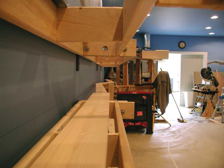
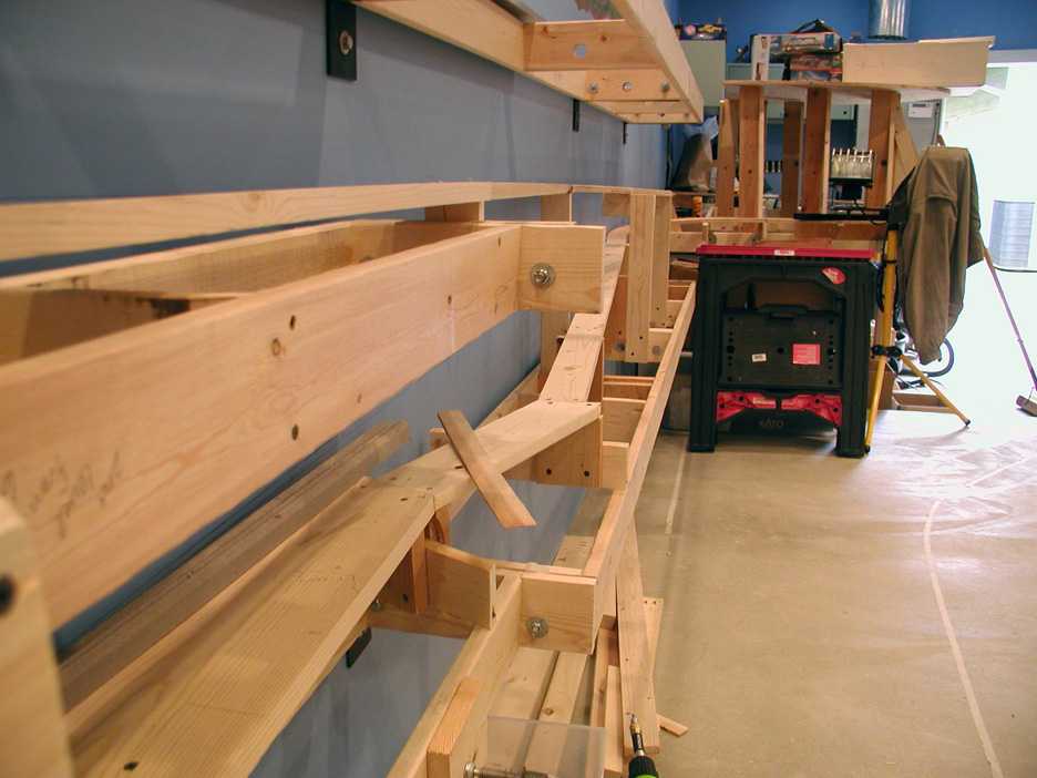
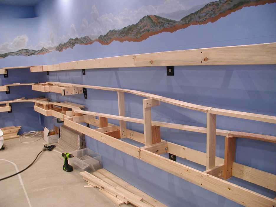
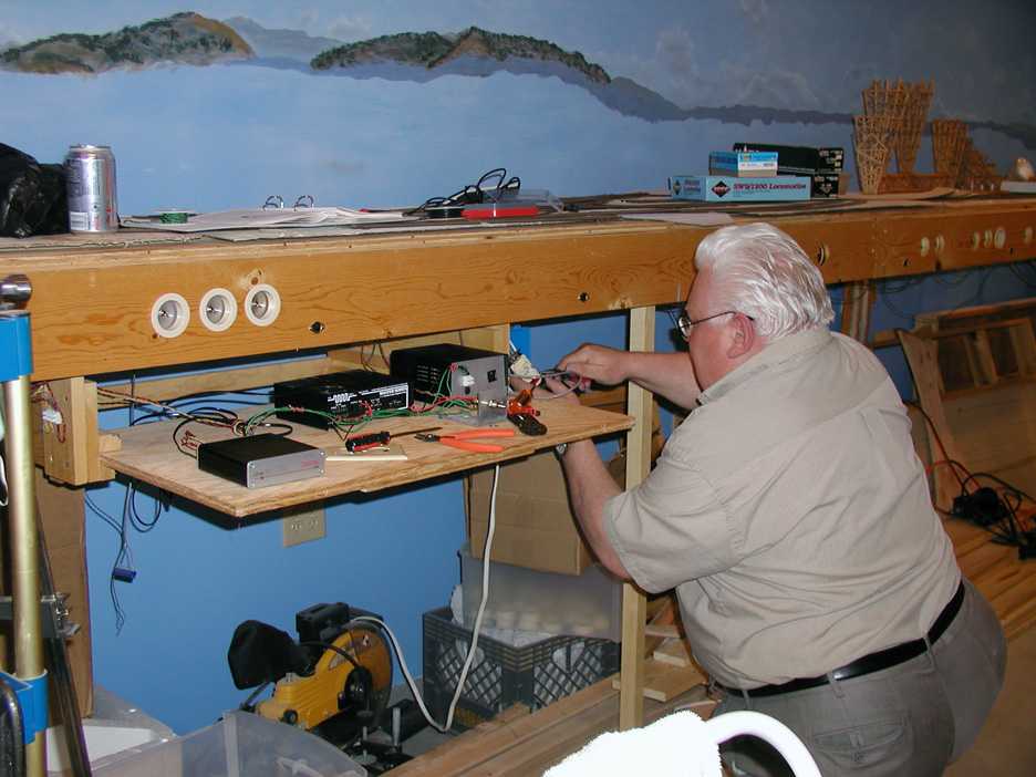
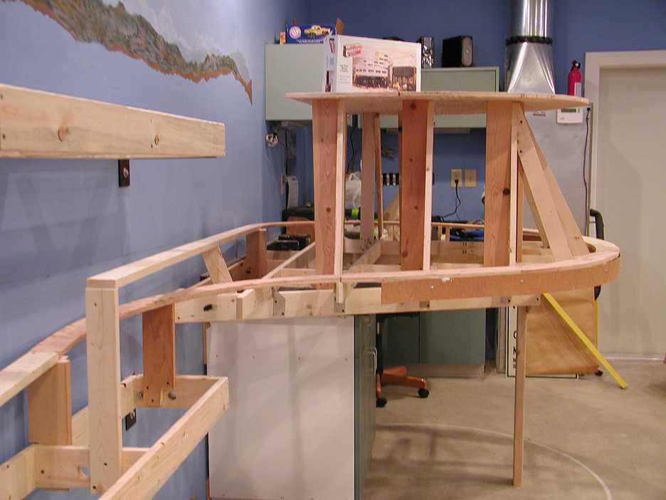
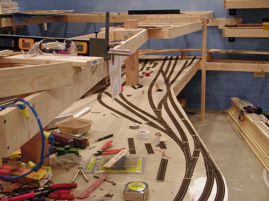
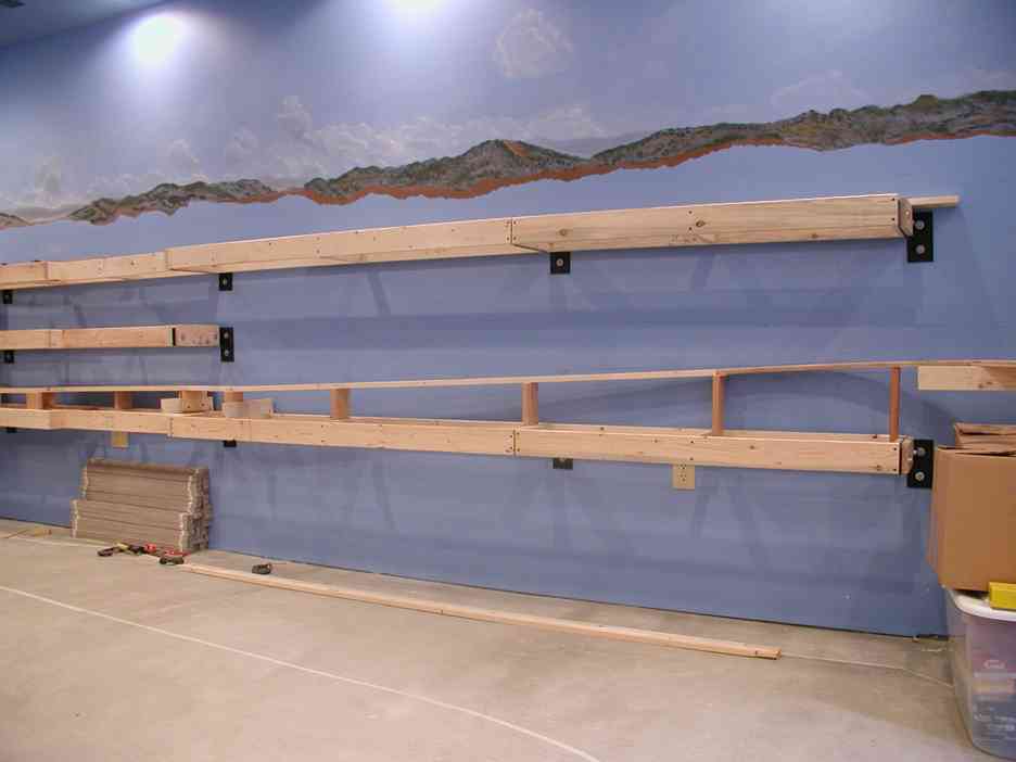
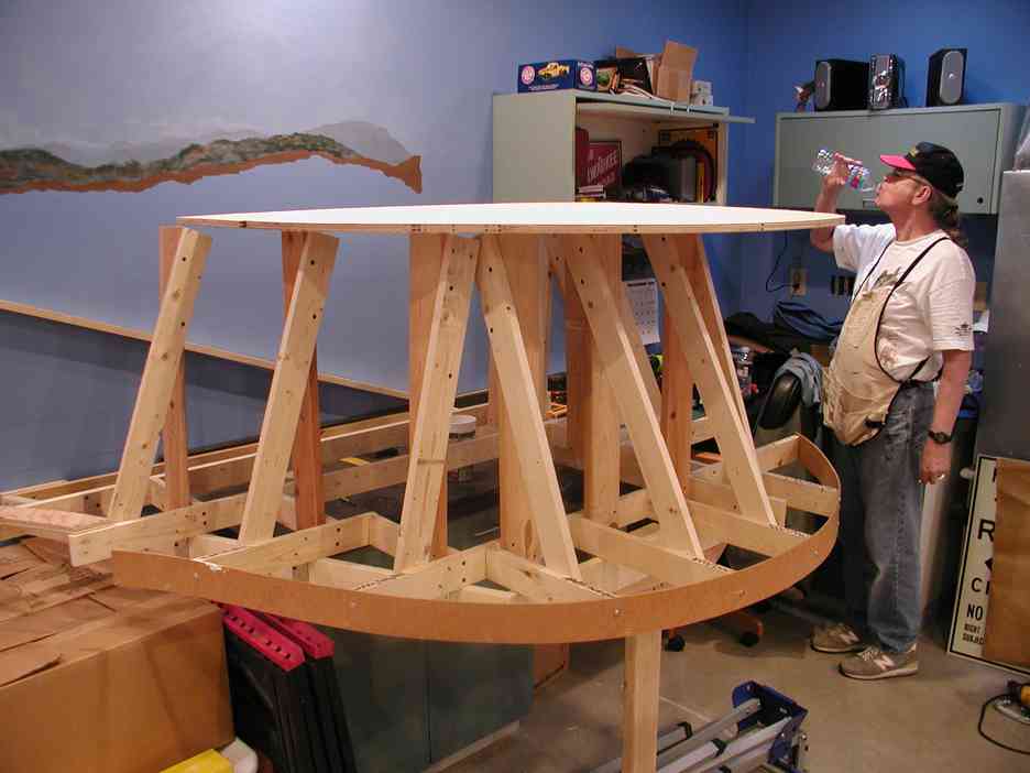
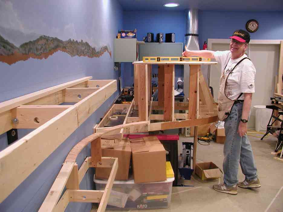
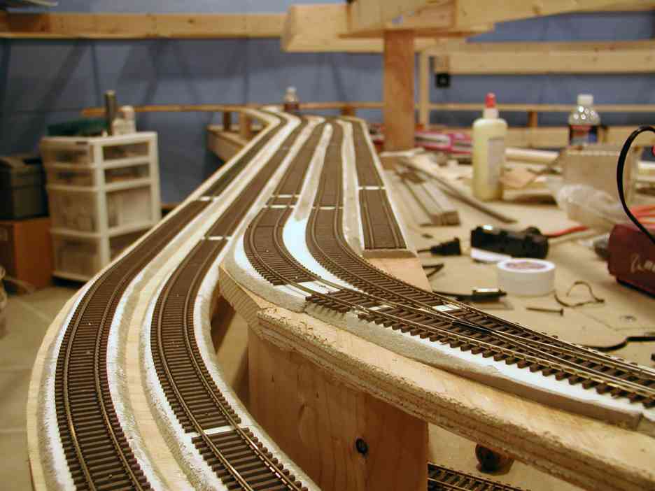
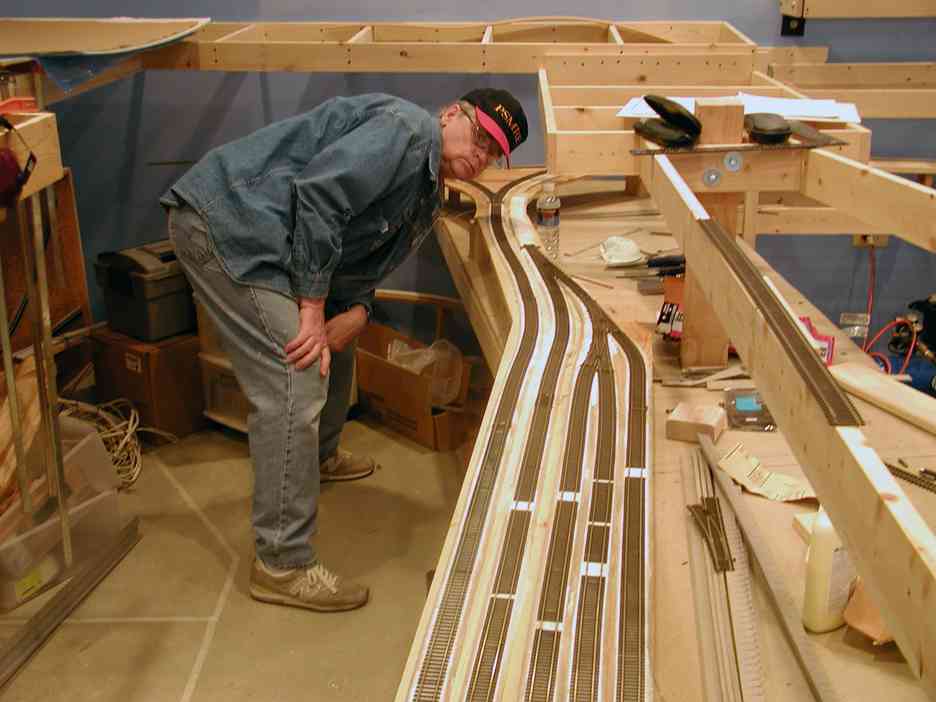
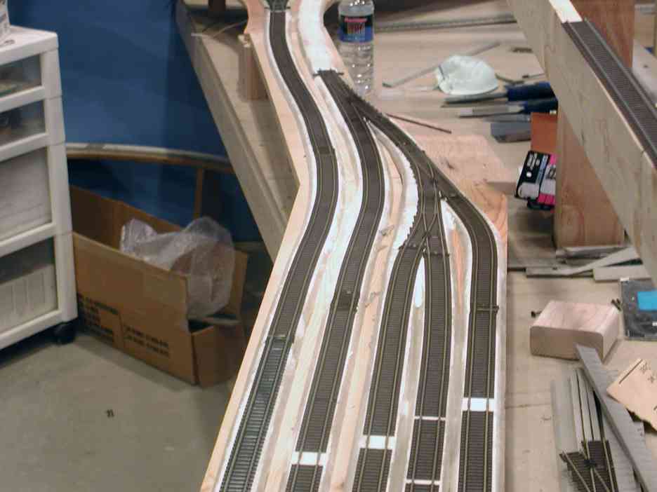
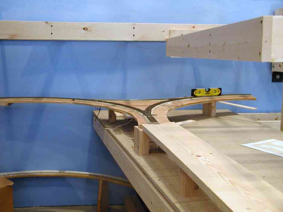
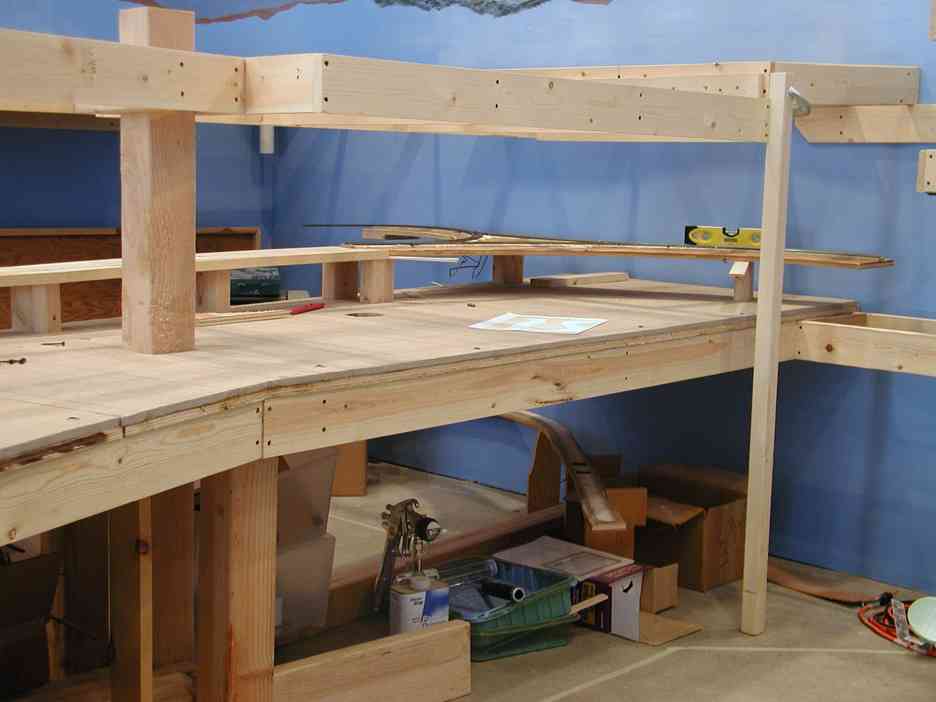
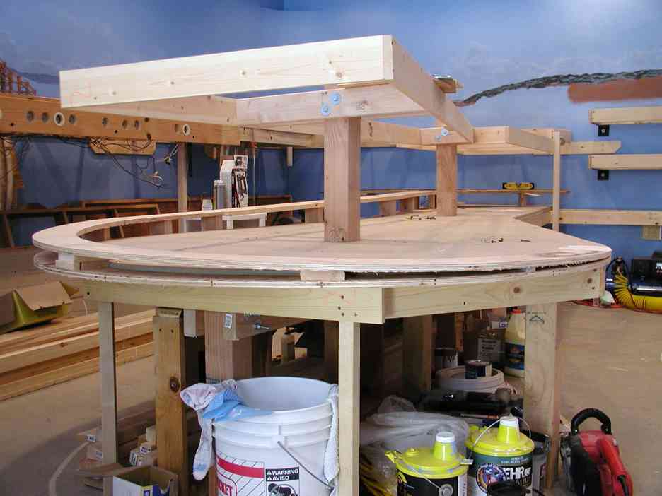
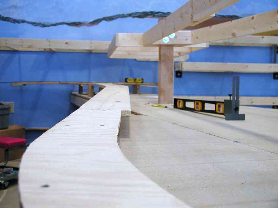
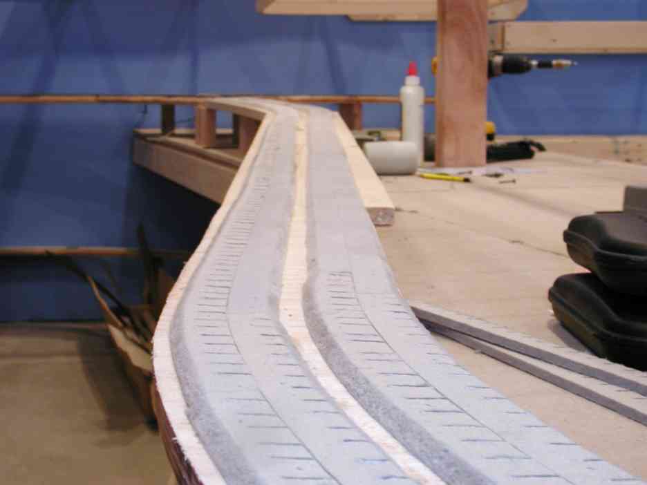
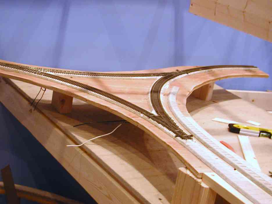
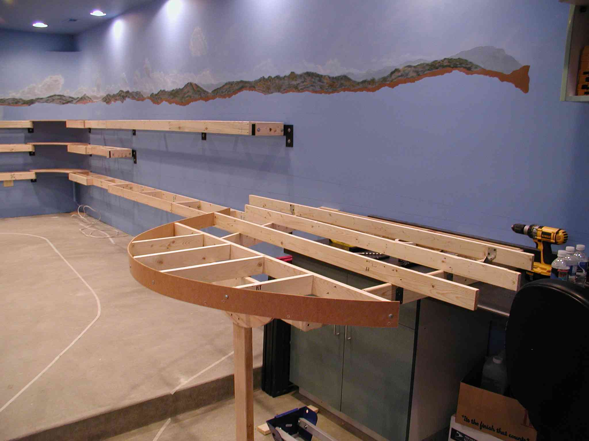
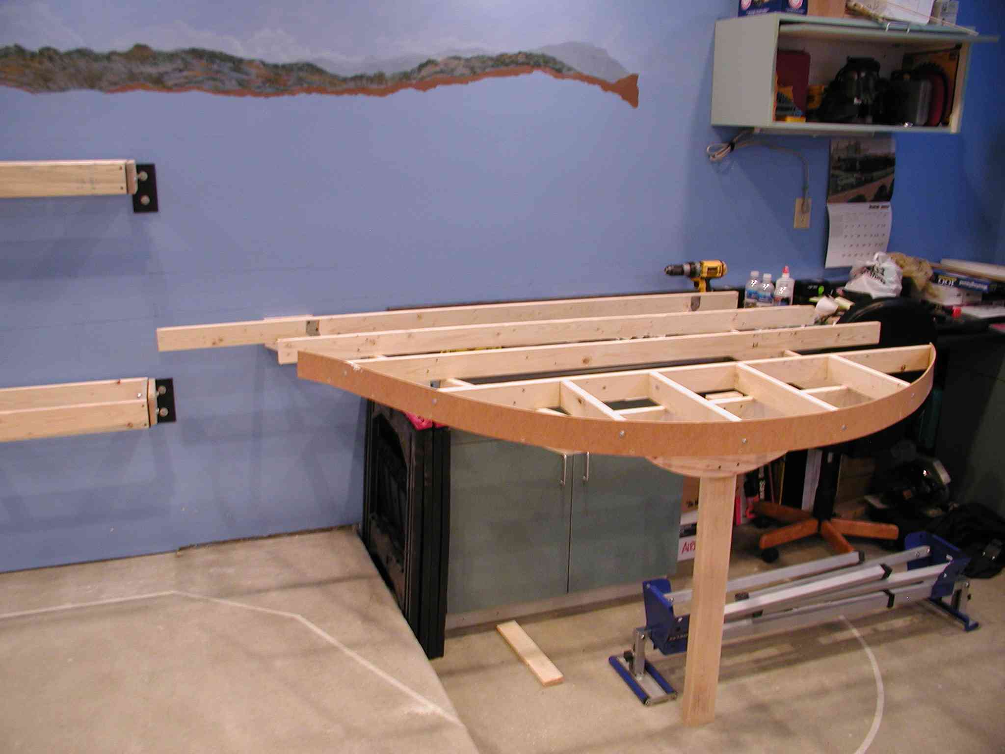
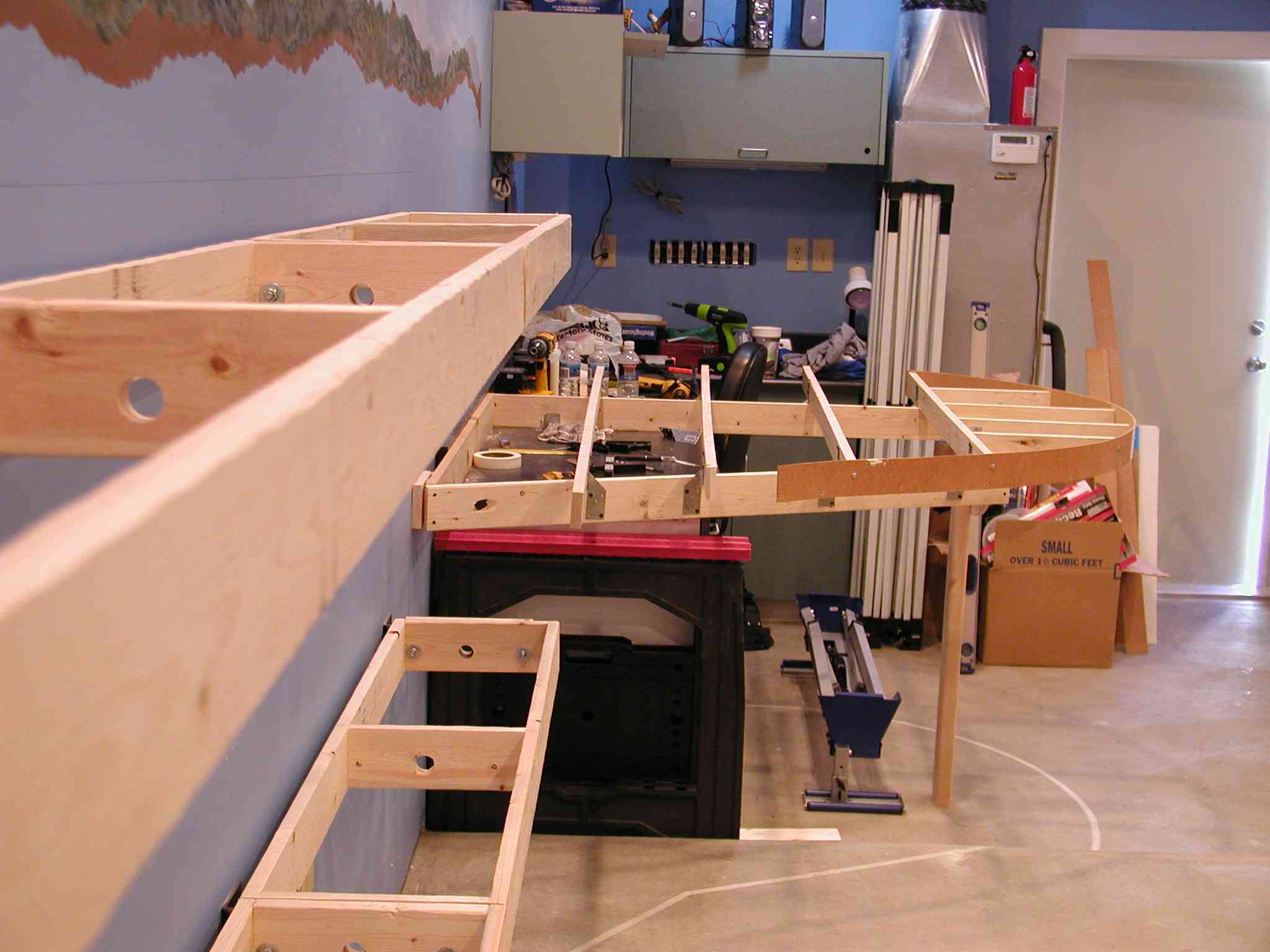
The new lower staging trackplan will be published in our next update, but we have settled on a small container operation. In addition, there will be three static staging tracks that will be used for preparation of operating sessions. The pictures below will address the construction of the main tracks entering into staging. Picture one is the yard itself. We first put down a series of pre-cut sheets of 1/2″ homasote. We used cadrail to determine the best use of the 4×8 sheets and the cut them out with a jigsaw, fine tuning the cuts once the sheets we put in place. We used plenty of glue, screws (with washers) and clamps to hold it down. Once dried, we removed the screws. In the second picture, we installed the wye from our old layout. This will give us the ability to turn trains, but also an added feature of a quick return to the opposite staging yard by running along the south wall. Once that was in place, we constructed the subroad all the way to the staging yard. The static staging tracks start just after the wye, but are not yet visible in these pictures.
The next quartet of pictures starts with Chief Engineer Wain Miller checking the transition from the subroadbed to the homasote in the staging yard. This was a tricky area and we were concerned about potential derail problems if this area were not smooth and track level. After much fine tuning and sanding, we believe the transition is solid. The next picture is the subroad heading up the grade toward the wye. In later updates you will note the static staging tracks just to the right of this mainline. Picture three is the same view only now we have installed the Homabed. Our method of installation is glue and brads from a brad nailer. We then spread our favorite non shrinking gap filler and once dried, sand it smooth before installing our track. The final pic is a second look at the lower wye, this time with the Homabed in place up to it and the passing track beginning to take its shape.

In our next edition of the update, we will have the new staging track plan on-line as well as views of the track we have in place. We are also trying to get the Lenz system out of mothballs and get something running. Looking forward to that red letter day on the RGW. Til next time….

January 2008

When we last updated the site, and I am truly sorry for the delay in getting back to you, we had completed the boxes along the north wall and were about to begin the construction of the NE blob. Our term the “blob” was derived from the teardrop look of our structure. It is a complex build, because it must be built in stages and will ultimately hold three levels of track and the town of Black Diamond, our key coal site.
The roadbed will be heading upgrade from the lower staging yard and then along the full length of the north wall before exiting in a 34 inch radius curve and looping around the front edge of the blob, before sweeping around at a 2.5% grade to continue along to the second level of the North wall. Here are some views of the blob and its construction:

The blob was designed to hold substantial weight and is anchored with multiple bolts along the north wall. The construction is standard L girder over a simple hexagonal frame. The single support at the front is a 2X4 to which we have attached a rounded gusset to ensure stability. The gusset is rounded because we will be accessing the drawers under the blob later, so no need to have any pointed edges that might catch on anyone or anything being moved around under the table. The masonite edging along the front is temporary to protect the cross beams and one’s hip! We will form a final masonite edge once track is in place and scenery is ready to be installed.

In future updates, we will detail how the multiple levels of track will work in concert with the scenery to define several viewing areas. In our next update, we will start work on the lower staging and start laying track.

Shopping Basket