The layout is always a work in progress and this page will be devoted to updating that progress. For review purposes, while there are numerous sections remaining from the initial design, much of that layout will ultimately be scrapped for key parts.
The benchwork is made of pine and all joints are made using a biscuit joiner. The lack of mechanical fasteners is a personal choice, but those who have spoken of the finished product have raved about its strength. At one point in the prior layout, we had two people up on the benchwork to prove that exact point. All subroadbed is made from 1/2 inch plywood and the roadbed is a product called California Roadbed, formerly known as Homabed. Track is code 83 flex, with Atlas being the primary source. Turnouts are from Atlas, mostly Custom Series, No. 6’s. We do make use of curved turnouts from Shinohara where needed.
All turnouts are thrown mechanically using Tortoise switch machines with a modified throw mechanism and are controlled using toggle switches embedded in the fascia of the benchwork. The operating system is Lenz Digital and din plugs are placed every 3 feet for ease of use and accessibility.
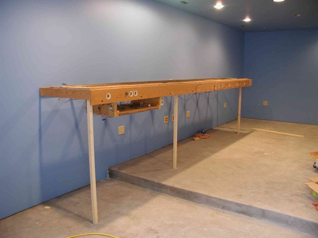
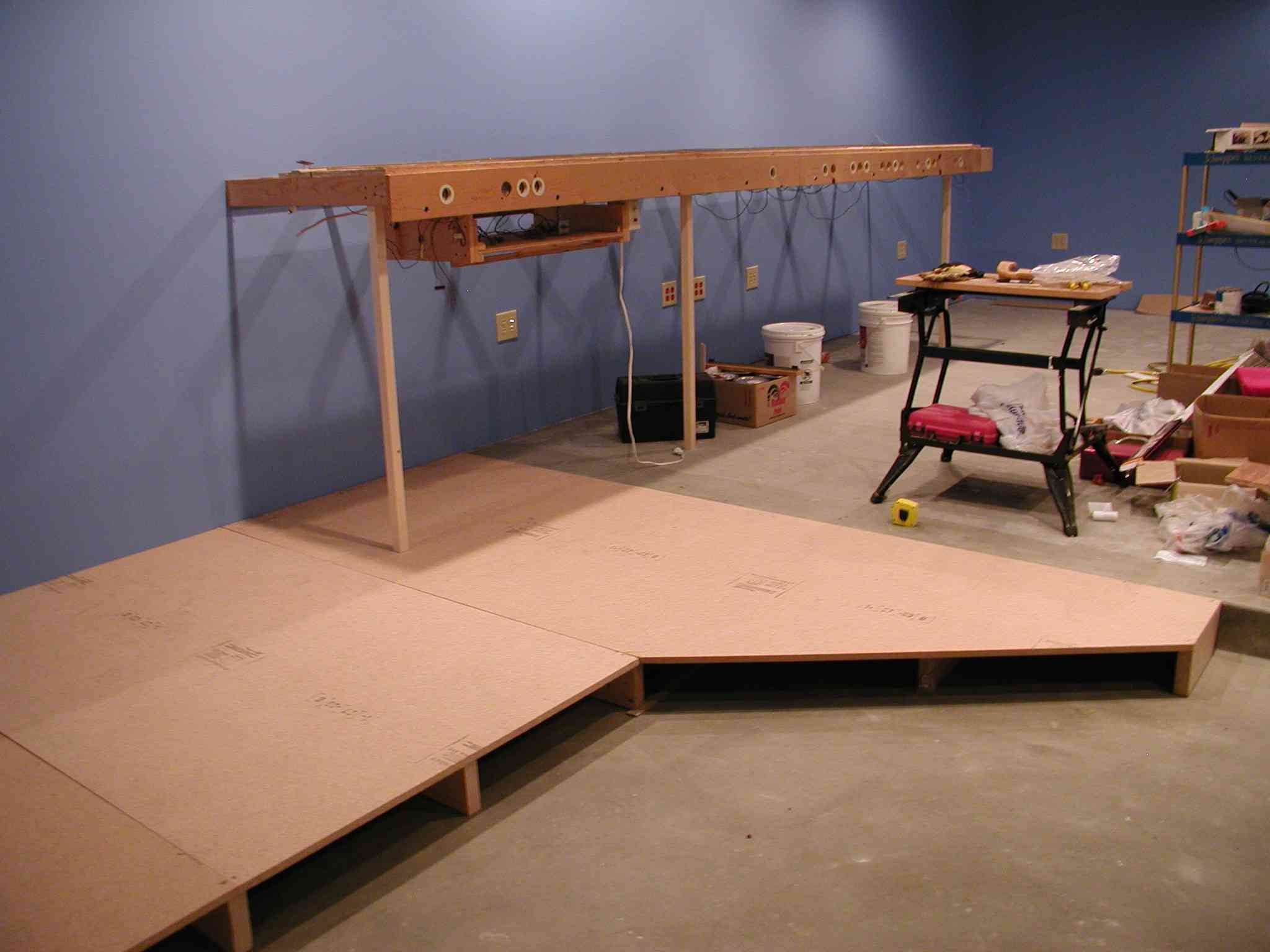
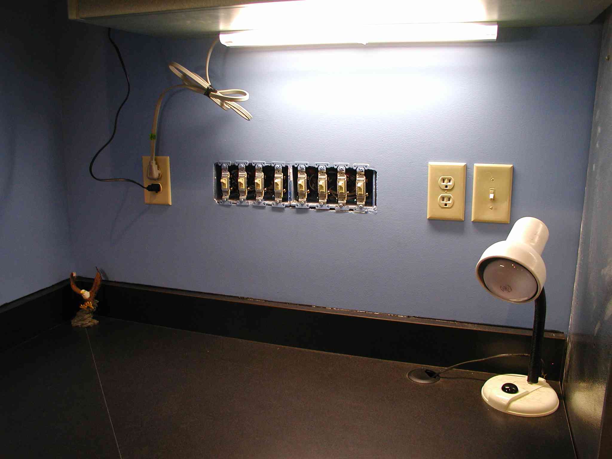
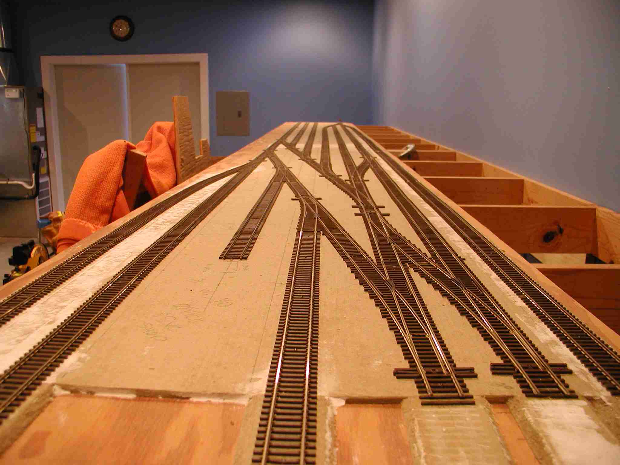
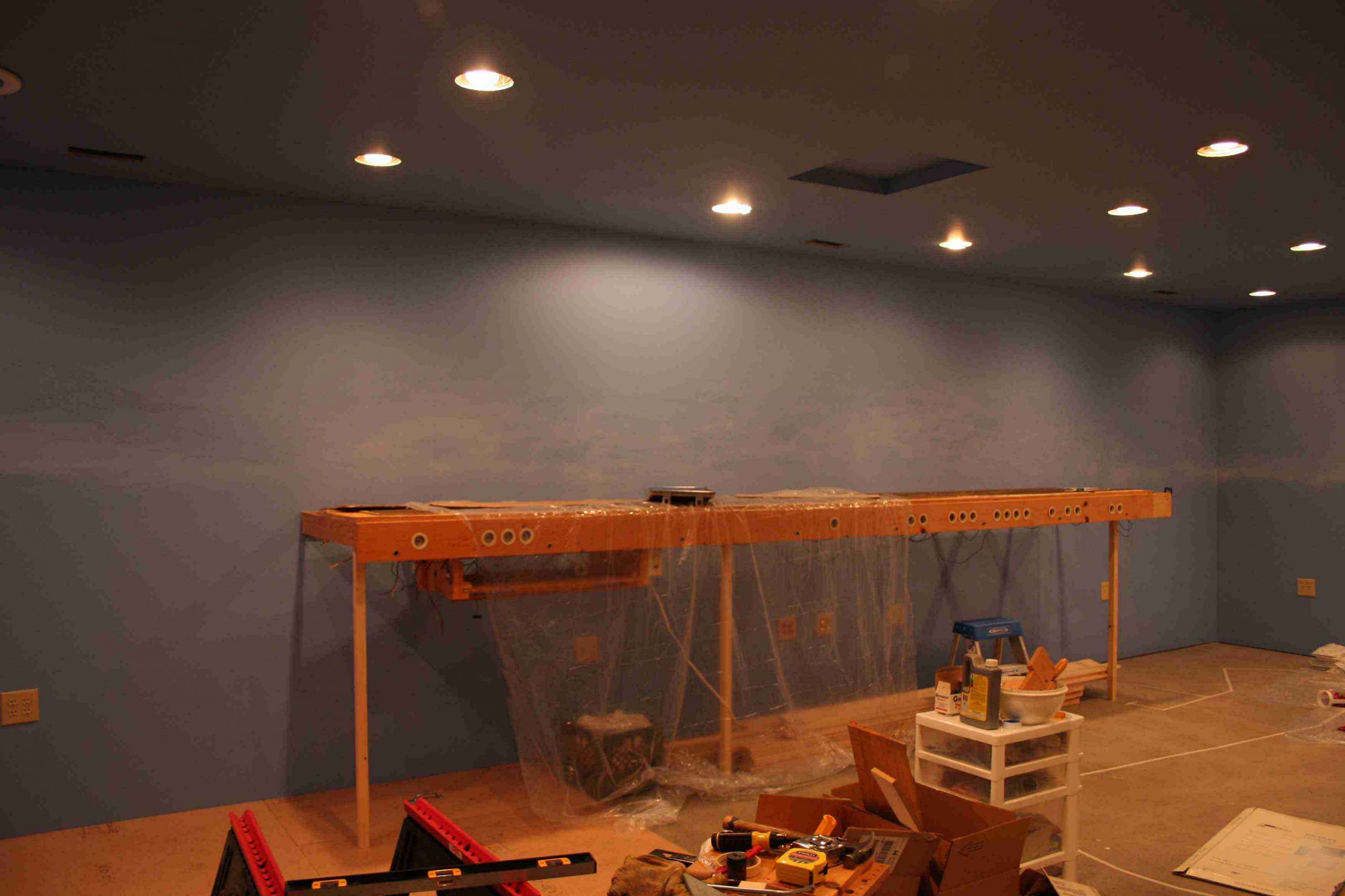
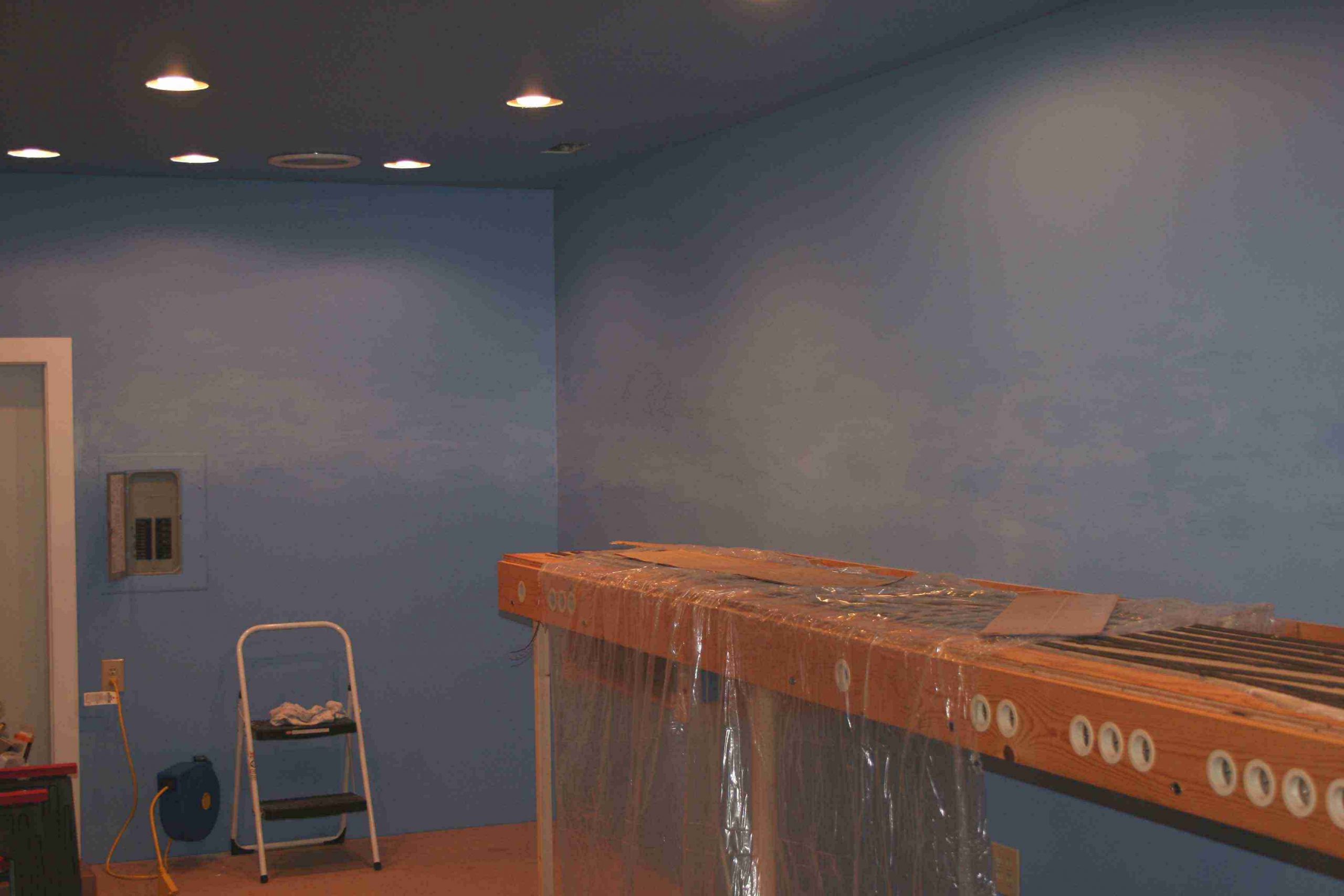
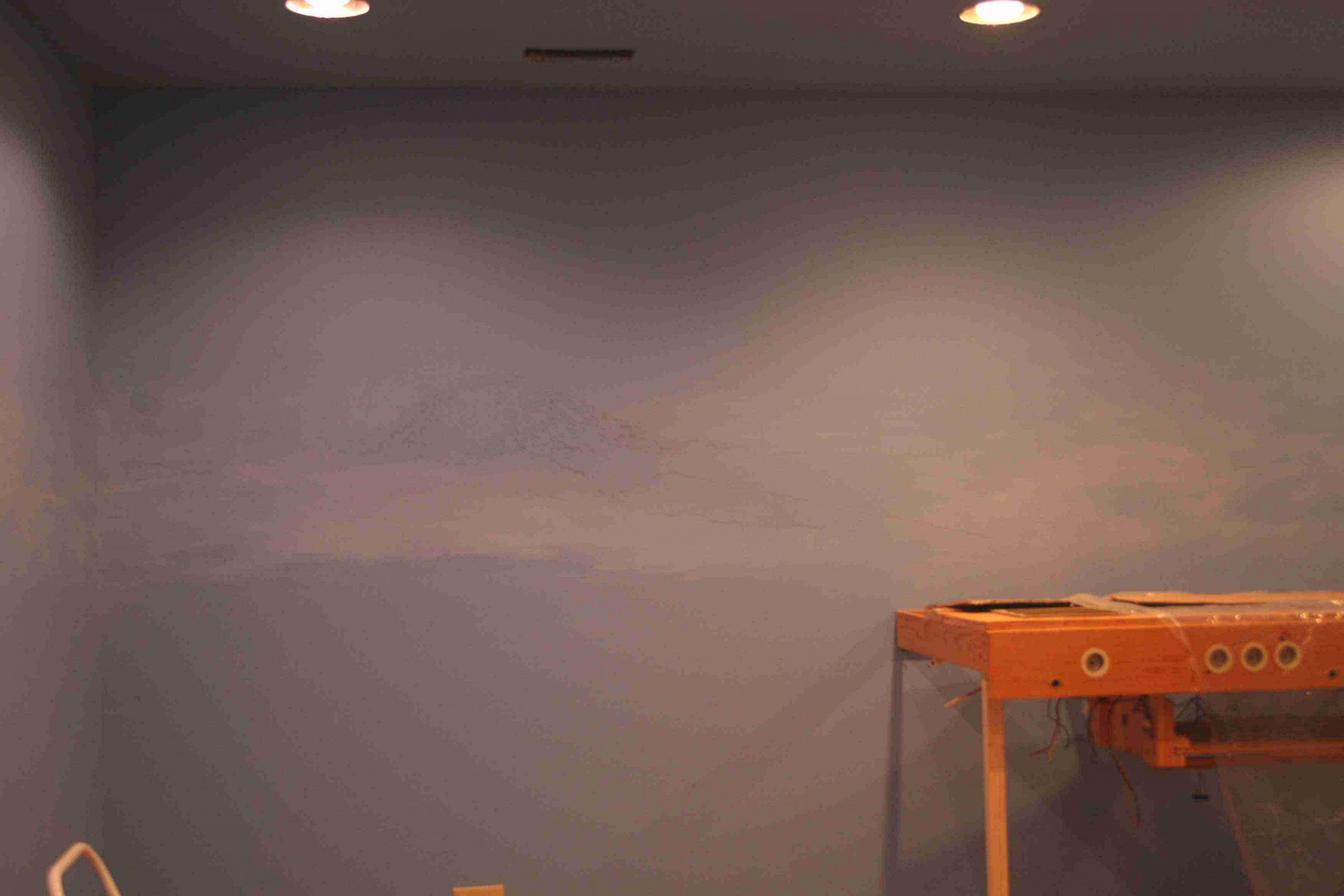
As of this update the only section of bench put in place is the main Renton Yard that was taken down intact from the prior layout. Here is a look at that section in place (looking toward the southwest), the control panel for the automated lighting system and the layout of the main Renton Yard:
The next section to go into place will be the southwest corner, this includes the addition of a Campbell Scale 134′ turntable. We will update this page as that takes place.
Previous
Next
Previous
Next
As of this update the only section of bench put in place is the main Renton Yard that was taken down intact from the prior layout. Here is a look at that section in place (looking toward the southwest), the control panel for the automated lighting system and the layout of the main Renton Yard:
The next section to go into place will be the southwest corner, this includes the addition of a Campbell Scale 134′ turntable. We will update this page as that takes place.
September/October 2005
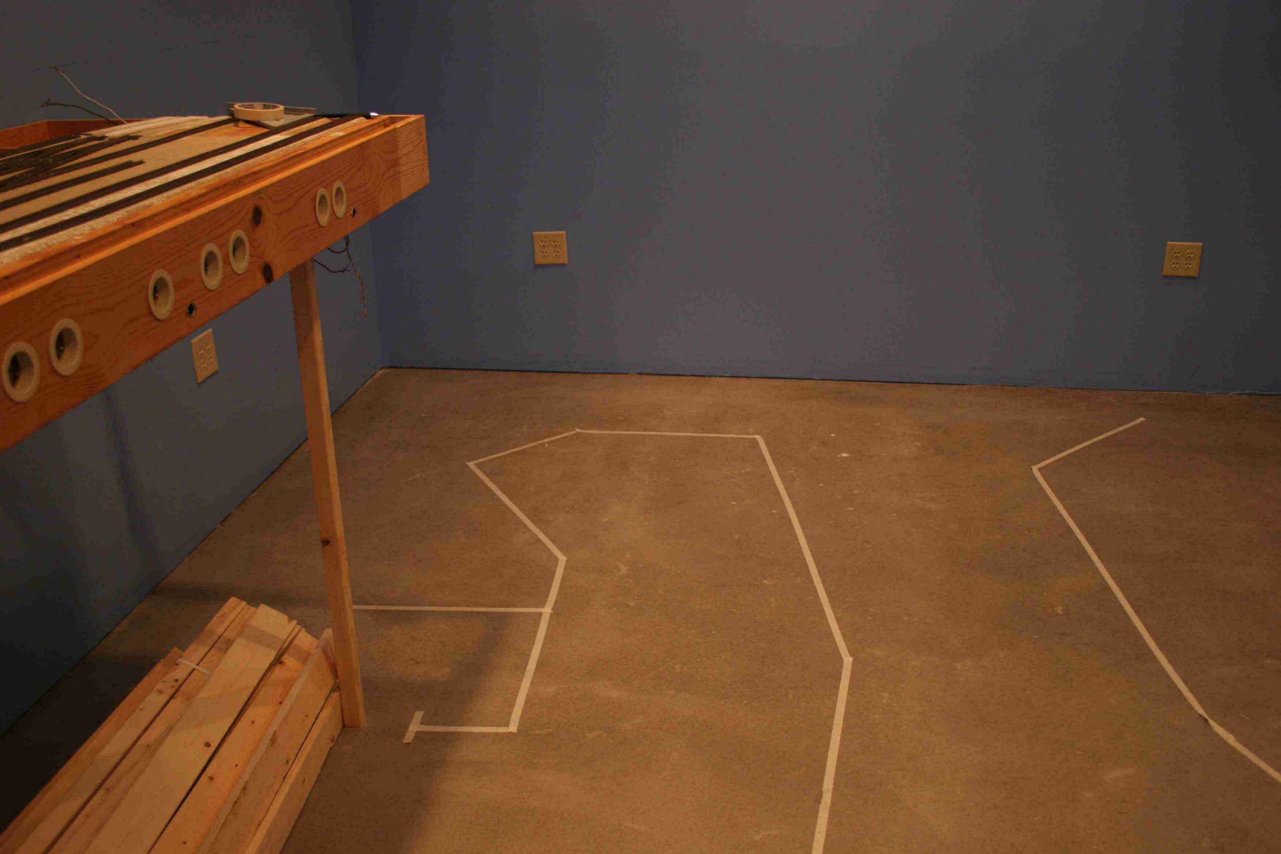
One of the many advantages of CADRAIL is that you can use the “Object Information” feature to provide accurate dimensions of virtually any item on the layout. For example, you can quickly determine the beginning and ending points of a line you have drawn in CADRAIL to represent the facing edge of your benchwork. As such, we recently spent a weekend addressing the SW Corner of the layout.
We first wanted to position the 134 ft. Campbell Scale turntable at the west end of Renton Yard. We determined that the location we originally set for the turntable limited our use of the area to the west for house tracks. Therefore we moved the turntable about 16 inches to the east, freeing up space for buildings, house tracks and other items to be determined.
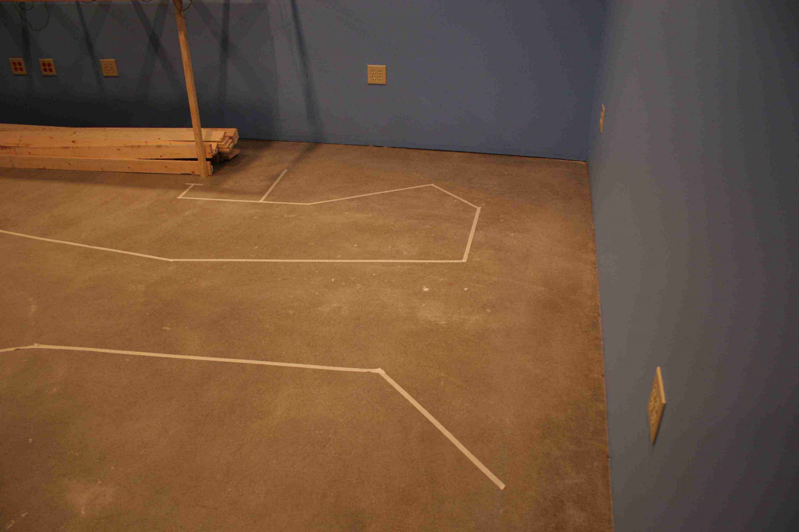
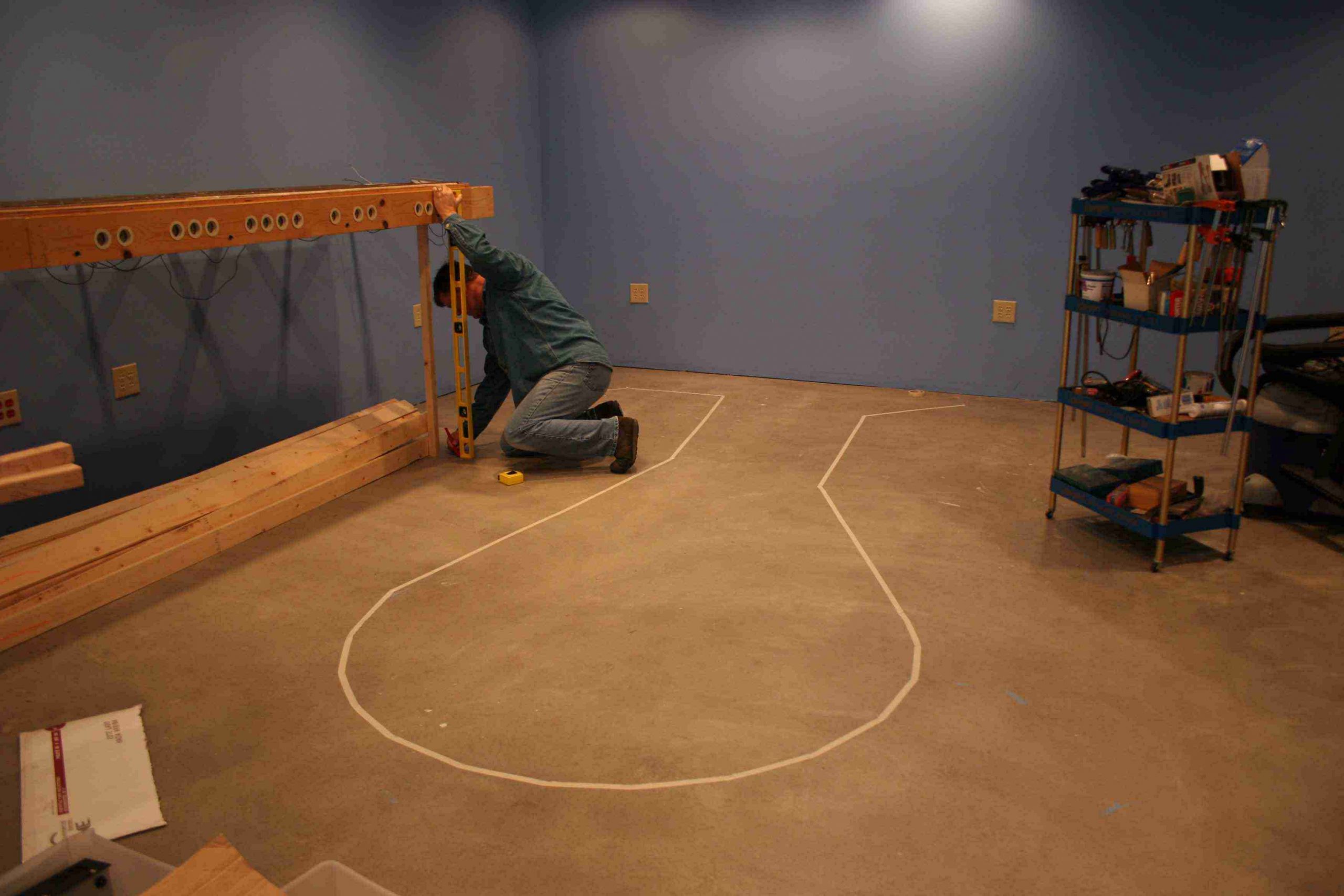
Once we had that issue tackled, we set out to dimension the SW Corner and the Western finger table. To make certain that the layout design would actually fit in the corner and still provide decent aisle space, we brought in the computer, called up CADRAIL and then used the SW corner as (0,0) on the (x,y) coordinate scale. After that, we found each point on the table, and ran masking tape on the floor to represent the front edge of the benchwork. As you can see from the pictures, so far so good.
Previous
Next
Previous
Next
Once we had that issue tackled, we set out to dimension the SW Corner and the Western finger table. To make certain that the layout design would actually fit in the corner and still provide decent aisle space, we brought in the computer, called up CADRAIL and then used the SW corner as (0,0) on the (x,y) coordinate scale. After that, we found each point on the table, and ran masking tape on the floor to represent the front edge of the benchwork. As you can see from the pictures, so far so good.
Previous
Next
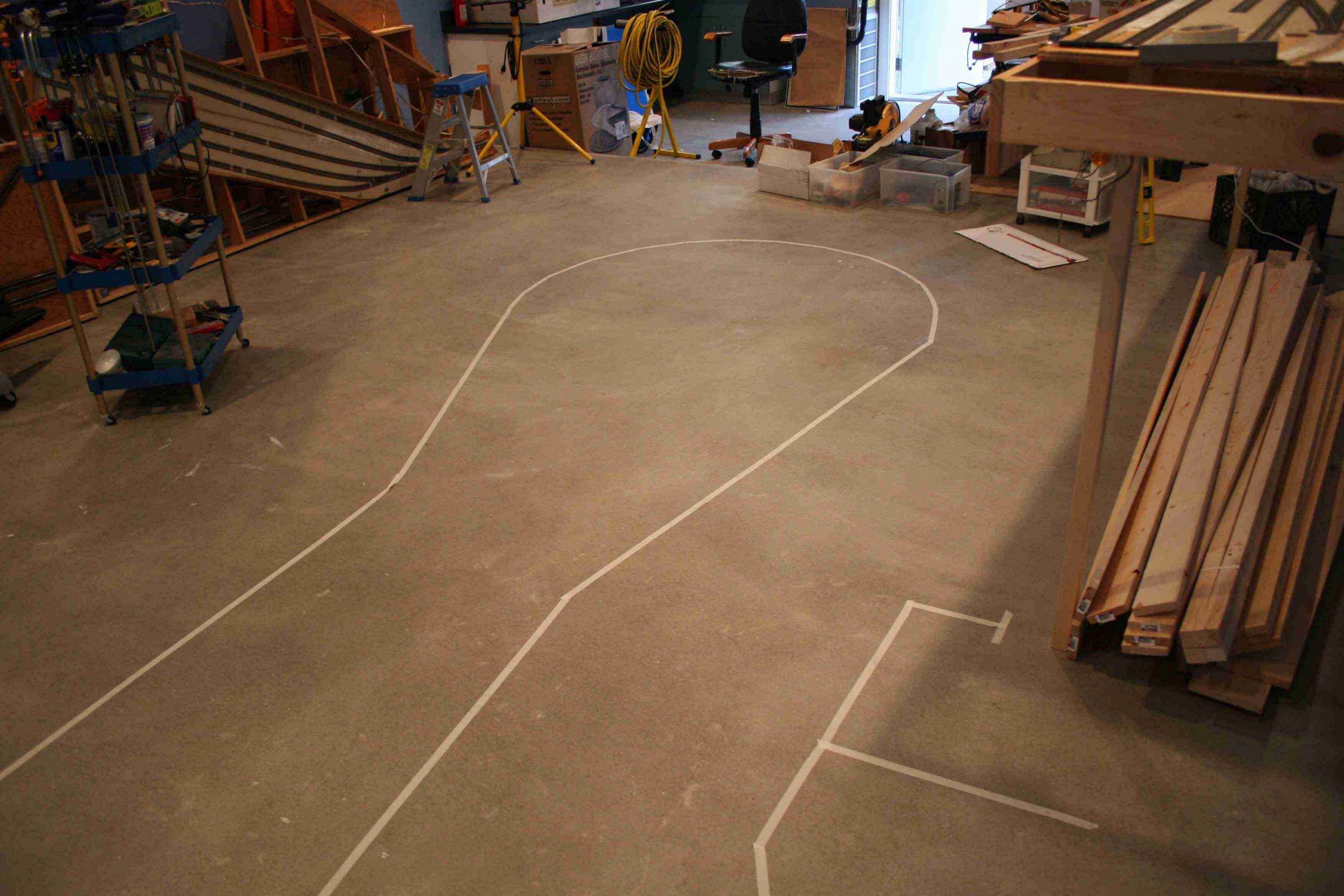
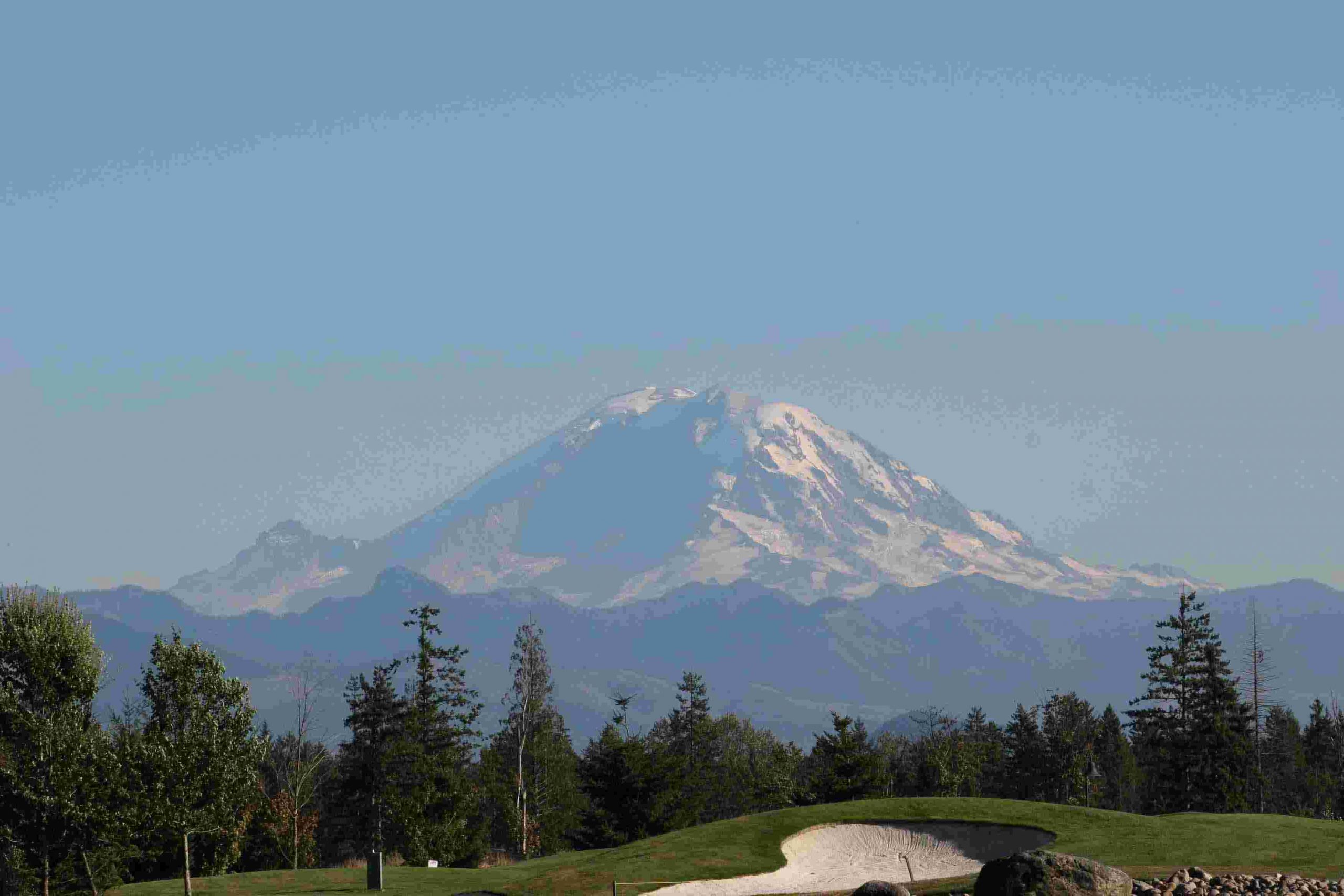
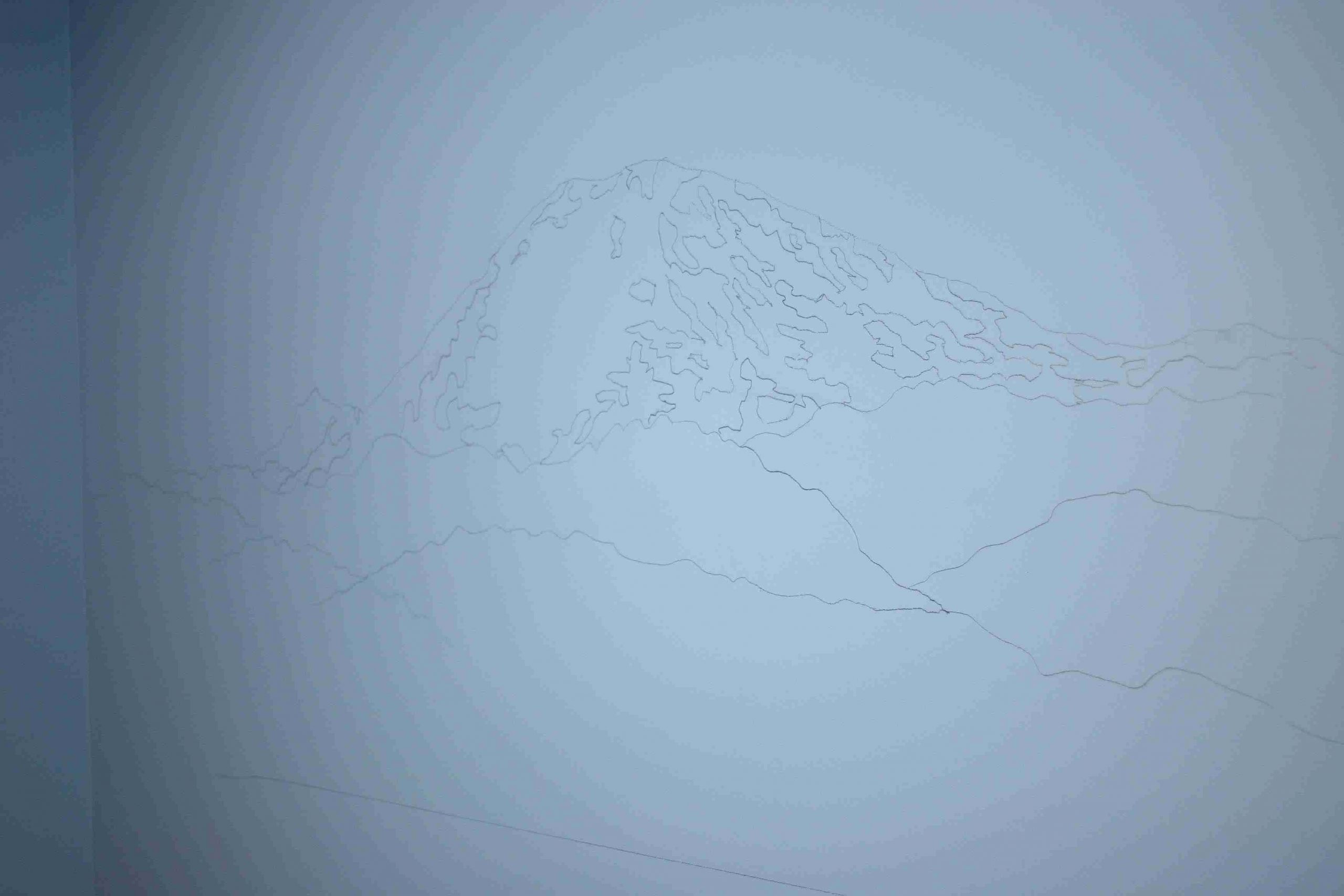
In addition to the preliminary scaling of the benchwork, a side project included the tracing of a picture of Mt. Rainier on the SE corner of the layout. While this picture doesn’t do the finished product justice, you get the idea where we are going with it. Mt. Rainier is by far the most distinct physical feature in this region and will command a strong presence on the RGW.
Previous
Next
In addition to the preliminary scaling of the benchwork, a side project included the tracing of a picture of Mt. Rainier on the SE corner of the layout. While this picture doesn’t do the finished product justice, you get the idea where we are going with it. Mt. Rainier is by far the most distinct physical feature in this region and will command a strong presence on the RGW.
During the weekend of October 8, we decided to continue the development of the backdrop. As you can see from the picture above right, the first stage is penciling out the distant images of hills and in our case, mountains. The next step is to mist in white and blend it in with varying shades of the background blue, gradually fading it into the existing color the closer we get to the ceiling. Our method was to first mix up a 90%/10% mixture of hidden lake blue and white (with a hint of gray) to use for blending. We then shot about a 4 ft wide by 2 ft long section of the white on the backdrop. Using two 2 inch brushes, we worked the color onto the wall, adding the blue/white mix where needed to create the allusion of mist on the wall. This is just the first of several coats. Notice how the mist brings out the penciled in Mt Rainier. Here are the results:
Previous
Next
Previous
Next
During the weekend of October 8, we decided to continue the development of the backdrop. As you can see from the picture above right, the first stage is penciling out the distant images of hills and in our case, mountains. The next step is to mist in white and blend it in with varying shades of the background blue, gradually fading it into the existing color the closer we get to the ceiling. Our method was to first mix up a 90%/10% mixture of hidden lake blue and white (with a hint of gray) to use for blending. We then shot about a 4 ft wide by 2 ft long section of the white on the backdrop. Using two 2 inch brushes, we worked the color onto the wall, adding the blue/white mix where needed to create the allusion of mist on the wall. This is just the first of several coats. Notice how the mist brings out the penciled in Mt Rainier. Here are the results:
December 2005
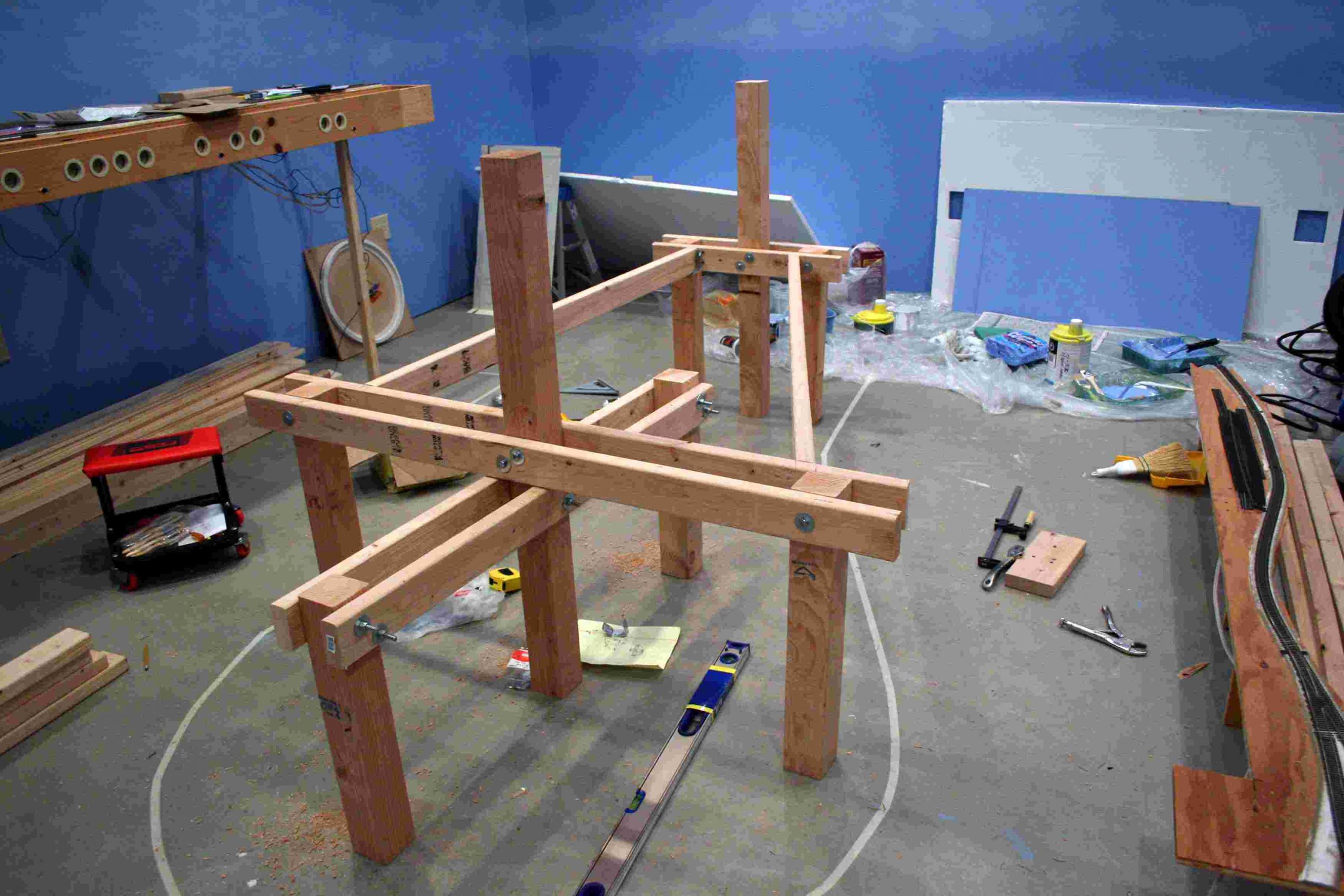
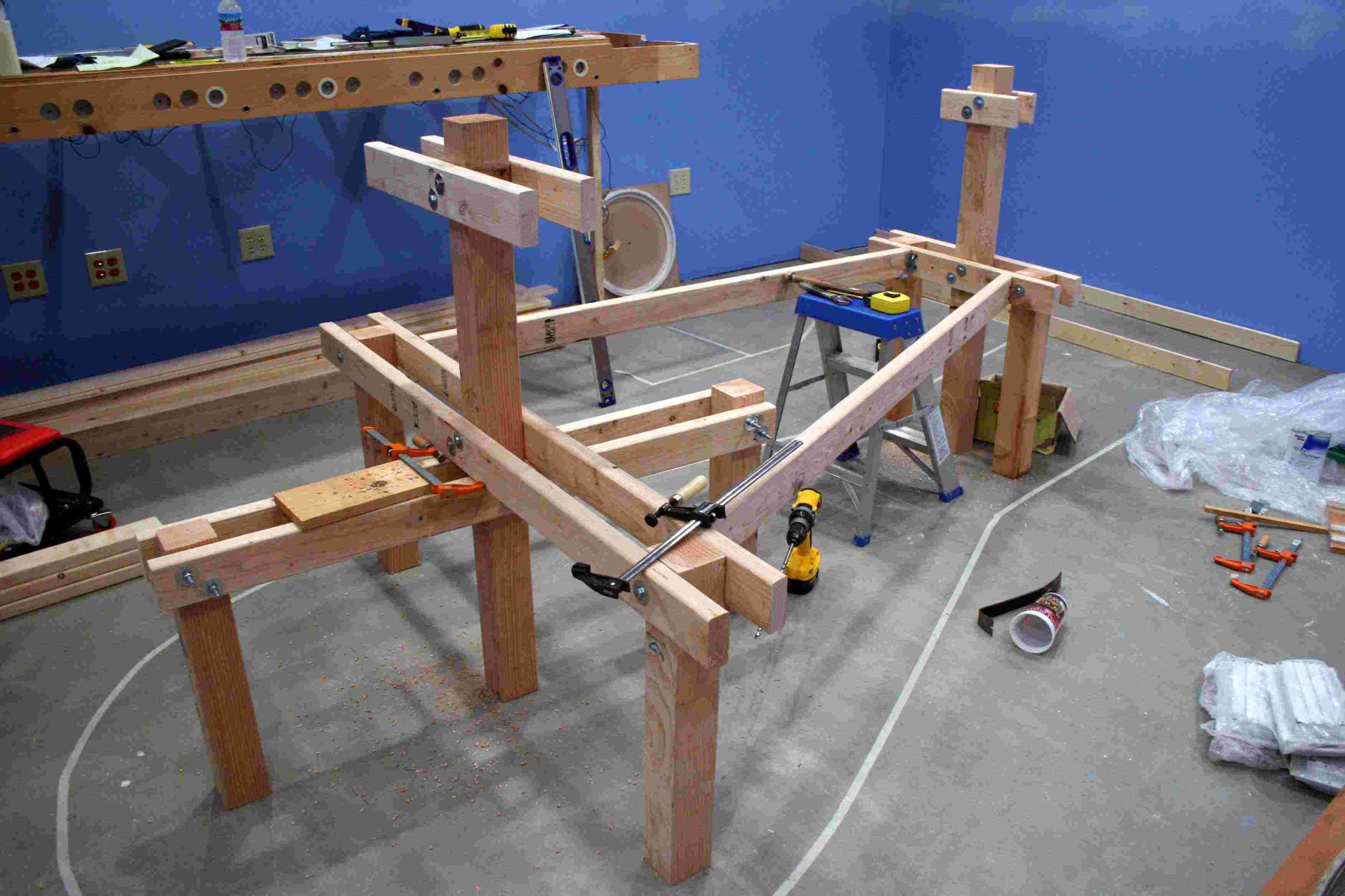
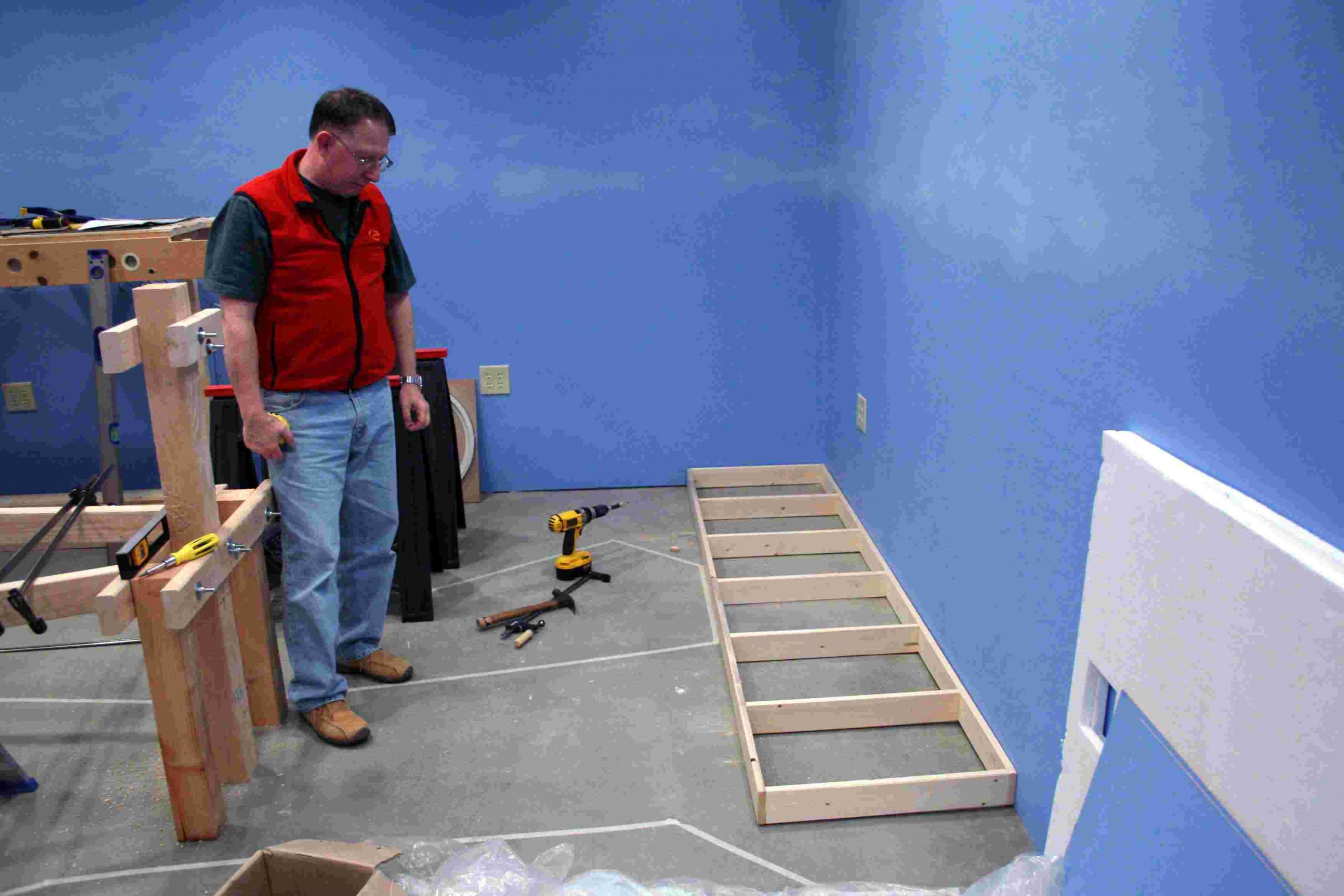
A solid 7 hours of work this past weekend produced some great progrAs reviewed in the October update, the use of CADRAIL’s object information feature allowed us to dimension the table sections on the floor in masking tape. Our latest work sessions involved the construction of the framework for the Southwest Finger Table and the transition tables from the in-place Renton Yard. As you can see from the pictures, we have engineered this table to fully support two full railroads, the primary visible railroad and the staging tracks that will support operation on the RGW. We have elected to scenic many areas of the hidden staging yards and access tracks so that the visible experience to the visitor will be enhanced and will provide the operator with more opportunity to follow the progress of his/her train.ess on the lower section of the RGW. In the lower staging yard, the three static staging tracks were put in place and are shown in our first three pics below. With the exception of a few replacement ties and a little fine tuning on the rail joiners, this section is complete.
Our next step will be to add stringers from the eastern edge of the table to the southwestern wall table. These stringers will be 1×4 L-girders that will then support north-south cross-members, which will form the base for risers to support our subroadbed.
If you look carefully, you can see that we have also notched the Renton Yard table to begin supporting the turntable, which is visible on the floor in the background.
Previous
Next
Previous
Next
Our next step will be to add stringers from the eastern edge of the table to the southwestern wall table. These stringers will be 1×4 L-girders that will then support north-south cross-members, which will form the base for risers to support our subroadbed.
If you look carefully, you can see that we have also notched the Renton Yard table to begin supporting the turntable, which is visible on the floor in the background.